
This article welcomes non-commercial reprints, please indicate the source when reprinting.
Statement: For collection only, for easy reading.
― Savir, Zhihu Column: 11. RDMA Shared Receive Queue
We briefly introduced the concept of SRQ in 【3. Basic Elements of RDMA】 . This article will take you through more details about SRQ.
# Basic Concepts
# What is SRQ?
The full name is Shared Receive Queue, literally translated as a shared receive queue. We know that the basic unit of RDMA communication is QP, and each QP consists of a send queue SQ and a receive queue RQ.
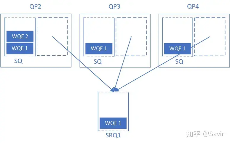
SRQ is designed by the IB protocol to save resources for the receiver. We can share an RQ with all associated QPs, and this shared RQ is called an SRQ. When a QP associated with it wants to post a receive WQE, it is filled into this SRQ. Then, whenever the hardware receives data, it stores the data in the specified location based on the content of the next WQE in the SRQ.
# Why use SRQ
Under normal circumstances, the number of tasks we issue to SQ is far greater than the number of tasks issued to RQ. Why is that? Please first recall which types of operations use SQ and which use RQ.
SEND/WRITE/READ all require the communication initiator to issue a WR to the SQ, and only the RECV operation paired with SEND requires the communication responder to issue a WR to the RQ (the Write operation with immediate value will also consume Receive WR, which we haven’t discussed yet). As we know, the SEND-RECV pair of operations is usually used for transmitting control information, while WRITE and READ are the main operations for performing large amounts of remote memory read and write operations, so naturally, the usage rate of SQ is much higher than that of RQ.
Each queue is an entity, occupying memory and on-chip storage space of the network card. In commercial scenarios, the number of QPs can reach hundreds of thousands or even higher, which places high demands on memory capacity. Memory is bought with hard-earned money, and SRQ is a mechanism designed by the IB protocol to save user memory.
Let’s take a look at the official explanation in the agreement for why SRQ is used (Section 10.2.9.1):
Without SRQ, an RC, UC or UD Consumer must post the number of receive WRs necessary to handle incoming receives on a given QP. If the Consumer cannot predict the incoming rate on a given QP, because, for example, the connection has a bursty nature, the Consumer must either: post a sufficient number of RQ WRs to handle the highest incoming rate for each connection, or, for RC, let message flow control cause the remote sender to back off until local Consumer posts more WRs.
• Posting sufficient WRs on each QP to hold the possible incoming rate, wastes WQEs, and the associated Data Segments, when the Receive Queue is inactive. Furthermore, the HCA doesn’t provide a way of reclaiming these WQEs for use on other connections.
• Letting the RC message flow control cause the remote sender to back off can add unnecessary latencies, especially if the local Consumer is unaware that the RQ is starving.
In simple terms, without SRQ, because the receiver of RC/UC/UD does not know how much data the other end will send and when it will arrive, it must prepare for the worst-case scenario, preparing for the possibility of receiving a large amount of data suddenly, which means issuing a sufficient number of receive WQEs to the RQ. Additionally, the RC service type can use flow control mechanisms to exert backpressure on the sender, essentially telling the other end “I don’t have enough RQ WQEs here,” so the sender will temporarily slow down or stop sending data.
However, as we mentioned earlier, the first method, being prepared for the worst-case scenario, often results in a large number of RQ WQEs being idle and unused, which is a significant waste of memory. Although the second method doesn’t require issuing as many RQ WQEs, flow control comes at a cost, which is the increased communication latency.
And SRQ solves the above problem by allowing many QPs to share receive WQEs (as well as memory space for storing data). When any QP receives a message, the hardware will take a WQE from the SRQ, store the received data according to its content, and then the hardware will return the completion information of the receive task to the corresponding upper-level user through the Completion Queue.
Let’s take a look at how much memory can be saved by using SRQ compared to using a standard RQ1:
Assume that there are N pairs of QP on the node receiving data, and each QP may receive a consecutive M messages at random times (each message consumes a WQE from an RQ),
- If SRQ is not used, the user needs to issue N * M RQ WQEs in total.
- If using SRQ, the user only needs to issue K * M RQ WQEs, where K is much smaller than N.
This K can be configured by the user according to the business needs. If there is a large amount of concurrent reception, then set K to a larger value; otherwise, setting K to a single digit is sufficient to handle general situations.
We have saved a total of (N - K) * M RQ WQEs, and RQ WQEs themselves are not very large, approximately a few KB in size, which doesn’t seem to take up much memory. However, as mentioned earlier, what is actually saved is the memory space used to store data, which is a significant amount of memory. We will use a diagram to illustrate:
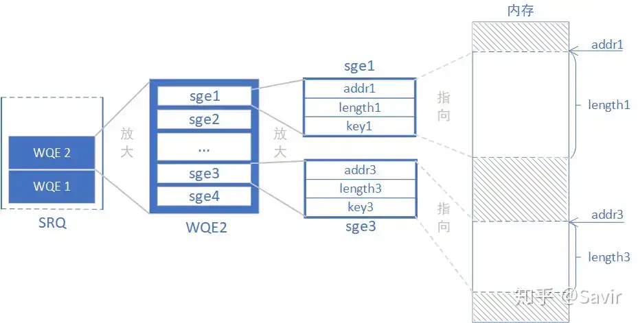
In the above diagram, there are two RQ WQEs in the SRQ. Let’s take a look at the contents of an RQ WQE, which are composed of several SGEs (Scatter/Gather Elements). Each SGE consists of a memory address, length, and key. With a starting address and length, an SGE can point to a contiguous memory region, and multiple SGEs can represent multiple discrete contiguous memory blocks. We refer to multiple SGEs as an SGL (Scatter/Gather List). SGEs are ubiquitous in the IB software protocol stack (and indeed very common throughout Linux), allowing very large memory regions to be represented with minimal space. IB users use SGEs to specify send and receive areas.
You can simply estimate the size of the memory region each sge can point to. The length is a 32-bit unsigned integer, which can represent 4GB of space. Assuming an RQ WQE can hold a maximum of 256 sge, then an RQ WQE would be a total of 1TB. Of course, in reality, it cannot be that large, this is just to intuitively inform the reader of the potential memory space an RQ WQE might occupy.
# SRQC
That is SRQ Context. Like QPC, SRQC is used to inform the hardware about attributes related to SRQ, including depth, WQE size, and other information, which will not be elaborated on in this article.
# SRQN
That is SRQ Number. Like QP, there may be multiple SRQs in each node. To identify and distinguish these SRQs, each SRQ has a serial number, called SRQN.
# PD of SRQ
In 【7. RDMA Protection Domain】 , we introduced the concept of Protection Domain, which is used to isolate different RDMA resources. Each SRQ must specify its own PD, which can be the same as the PD of its associated QP, or it can be different; SRQs can also use the same PD.
If a packet is received while using SRQ, it will only be properly received if the MR and SRQ being accessed are under the same PD; otherwise, an immediate error will occur.
# Asynchronous event
In the article 【10. RDMA Completion Queue】 , we introduced that the IB protocol classifies error types into immediate errors, completion errors, and asynchronous errors based on the method of error reporting. Among them, asynchronous errors are similar to interrupts/events, so we sometimes refer to them as asynchronous events. Each HCA registers an event handling function specifically for handling asynchronous events. Upon receiving an asynchronous event, the driver performs the necessary processing and further reports it to the user.
There is a special asynchronous event regarding SRQ, used to promptly notify upper-level users of the SRQ status, namely the SRQ Limit Reached event.
# SRQ Limit
SRQ can set a watermark/threshold, when the number of remaining WQEs in the queue is less than the watermark, this SRQ will report an asynchronous event. It reminds the user “The WQEs in the queue are about to run out, please issue more WQEs to prevent having no place to receive new data.” This watermark/threshold is called the SRQ Limit, and the reported event is called SRQ Limit Reached.
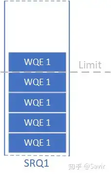
Because the SRQ is shared by multiple QPs, if the depth is relatively small, it is very likely that the WQE inside will suddenly run out. Therefore, the protocol is designed with this mechanism to ensure that users can promptly intervene in situations where the WQE is insufficient.
After reporting an asynchronous event, the value of SRQ Limit will be reset to 0 by the hardware (presumably to prevent continuously reporting asynchronous events to the upper layer). Of course, users can choose not to use this mechanism by simply setting the value of SRQ Limit to 0.
# User interface
# Control surface
Still the old four types—“Add, Delete, Modify, Query”:
- Create SRQ
When creating an SRQ, similar to a QP, all software and hardware resources related to the SRQ are allocated. For example, the driver will request an SRQN, allocate space for the SRQC, and fill in the configuration. When creating an SRQ, you must also specify the depth of each SRQ (how many WQEs it can store) and the maximum number of sges per WQE.
- Destroy SRQ
Destroy all related software and hardware resources of SRQ.
- Modify SRQ
In addition to attributes such as SRQ depth, the value of SRQ Limit is also set through this interface. Because the value of the watermark is cleared every time an SRQ Limit Reached event occurs, the user needs to call Modify SRQ to reset the watermark each time.
- Query SRQ
It is usually used to query the configuration of the waterline.
# Data surface
# Post SRQ Receive
Just like Post Receive, it issues a receive WQE to the SRQ, which contains information about the memory block used as the receive buffer. It is important to note that the subject is SRQ and has nothing to do with QP. Currently, the user is not concerned with which QP this SRQ is associated with.
# The difference between SRQ and RQ
In terms of functionality, both SRQ and RQ are used to store received task requests, but due to the shared nature of SRQ, there are some differences between it and RQ.
# State machine
We introduced in 【9. RDMA Queue Pair】 that QP has a complex state machine, and the sending and receiving capabilities of QP vary in different states. However, SRQ only has two states: non-error and error.
Regardless of the state, users can issue WQEs to the SRQ. However, in an error state, the associated QP cannot receive data from this SRQ. Additionally, in an error state, users cannot query or modify the attributes of the SRQ.
When a QP is in an error state, it can be returned to the RESET state through Modify QP, but for SRQ, it can only exit the error state by destroying it.
# Receiving process
For a QP, RQ and SRQ cannot be used simultaneously, one must be chosen. If a WQE is issued to the RQ of a QP that is already associated with SRQ, an immediate error will be returned.
Let’s compare the reception processes of SRQ and RQ. The content of this section is a key point of this article, and I believe that after reading it, readers will have a more complete understanding of the SRQ mechanism.
# RQ’s receiving process
First, let’s revisit the receiving process of a regular RQ (for the complete process on the sender’s side, please read 【4. RDMA Operation Types】 ):
Create QP.
Through the Post Recv interface, the user submits receive WQE to the RQ of QP2 and QP3, respectively. The WQE contains information about which memory region to place the received data.
The hardware receives the data.
Hardware discovery is sent to QP3, then WQE1 is taken from QP3’s RQ, and the received data is placed in the memory area specified by WQE1.
After the hardware completes data storage, it generates a CQE to CQ3 associated with RQ of QP3, reporting task completion information.
The user retrieves WC (CQE) from CQ3, and then takes data from the specified memory area.
The hardware receives the data.
The hardware discovery is sent to QP2, then WQE1 is extracted from the RQ of QP2, and the received data is placed in the memory area specified by WQE1.
After the hardware completes data storage, it generates a CQE for CQ2 associated with RQ of QP2, reporting task completion information.
The user retrieves WC (CQE) from CQ2, and then takes data from the specified memory area.
# SRQ’s reception process
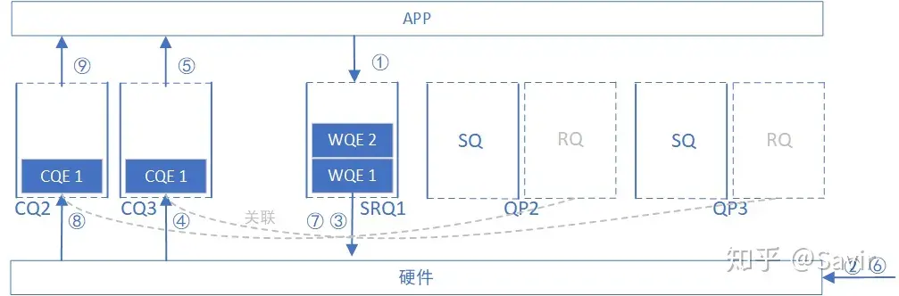
And the SRQ receiving process has some differences:
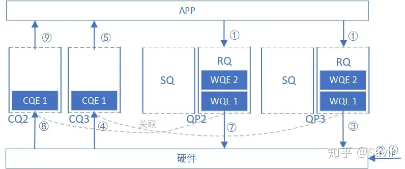
Create SRQ1, and create QP2 and QP3, both associated with SRQ1.
Through the Post SRQ Recv interface, the user issues two receive WQEs to SRQ1, containing information about which memory region to place the received data.
Hardware receives data.
The hardware discovery is sent to QP3, extracting the first WQE from SRQ1 (now it is WQE1), and storing the received data according to the content of the WQE.
Each WQE in the SRQ is “ownerless”, not associated with any QP. The hardware sequentially takes out the WQE according to the queue order and places the data inside.
The hardware discovers that the CQ associated with QP3’s RQ is CQ3, so it generates a CQE in it.
The user retrieves the CQE from CQ3 and takes data from the specified memory area.
Attentive readers may ask, when a user issues a WR, each WR specifies some memory regions for storing data in the future. However, an SRQ is a pool where each WQE points to several different memory regions. After the user receives a WC in the CQ corresponding to a certain QP, how do they know where the received data has been stored?
There is actually wr_id information in the WC, informing the user of which WR (WQE) designated memory area the data is placed in. Since the WR is issued by the user, the user naturally knows its specific location.
Hardware received data
The hardware discovery is sent to QP2, and the first WQE is taken from SRQ1 (now it is WQE2), and the received data is stored according to the content of the WQE.
The hardware discovers that the CQ associated with QP2’s RQ is CQ2, so a CQE is generated in it.
The user takes out the CQE from CQ2 and retrieves data from the specified memory area.
# Summary
This text first introduces the basic concept of SRQ, followed by its design purpose, related mechanisms, and user interface. Finally, it compares the SRQ receiving process with RQ. In actual business, the usage rate of SRQ is quite high, and it is hoped that readers can gain a deep understanding.
Let’s stop here, thank you for reading. In the next article, I will introduce the Memory Window.
# Relevant sections of the agreement
10.2.9 The design concept of SRQ and related operations
10.2.3 PD of SRQ and QP
10.8.2 The relationship between QP associated with SRQ and QP not using SRQ
10.8.5 SRQ related returns WC
11.5.2.4 Asynchronous Events
# Other references
Linux Kernel Networking - Implementation and Theory. Chapter 13. Shared Receive Queue ↩︎