
This article welcomes non-commercial reposting, please indicate the source.
Statement: For collection only, for convenient reading
― Savir, Zhihu Column: 9. Basic RDMA Service Types
# Queue Pair
We have previously provided a brief introduction to the concept of QP in the article “3. Basic Elements of RDMA” . This article will delve deeper into some details about QP.
# Review of Basic Concepts
First, let’s briefly review the basic knowledge about QP:
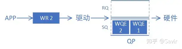
According to the description in the IB protocol, QP is a virtual interface between hardware and software. QP is a queue structure that sequentially stores tasks (WQE) issued by software to hardware. The WQE contains information such as where to retrieve data, how long the data is, and to which destination it should be sent.
Concept of QP
Each QP is independent and isolated from each other through PD, so a QP can be regarded as a resource exclusively used by a certain user, and a user can also use multiple QPs simultaneously.
QP has many types of services, including RC, UD, RD, and UC, etc. All source QPs and destination QPs must be of the same type to interact with each other.
Although the IB protocol refers to QP as a “virtual interface,” it is tangible:
On the hardware side, a QP is a storage space containing several WQEs. The IB network card reads the contents of the WQEs from this space and accesses the memory to store or retrieve data according to the user’s expectations. As for whether this storage space is memory space or on-chip storage space of the IB network card, the IB protocol does not impose restrictions, and each manufacturer has its own implementation.
In software, QP is a data structure maintained by the driver of the IB network card, which contains the address pointer of the QP and some related software attributes.
# QPC
In the article “5. RDMA Basic Service Types” , we mentioned that QPC stands for Queue Pair Context, which is used to store properties related to QP. The driver does store the software properties of QP, so if we can store QP properties in software, why do we still use QPC?
This is because QPC is mainly for hardware viewing and is also used to synchronize QP information between software and hardware.
We have mentioned that the entity of a QP on hardware is merely a segment of storage space, and the hardware knows nothing beyond the starting address and size of this space, not even the service type of this QP. There is also a lot of other important information, such as a QP containing several WQEs. How does the hardware know how many there are and which one it should currently process?
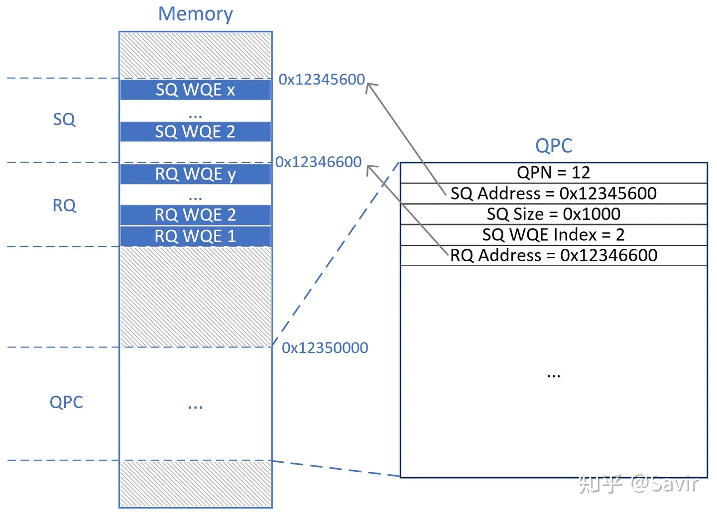
All of the above information can be structured into a data structure by the software, and memory space can be allocated for it. However, the software only sees virtual addresses, and these memory spaces are physically discrete; the hardware does not know where this data is stored. Therefore, the software needs to pre-allocate a large contiguous space through the operating system, namely QPC, to present this information to the hardware. The network card and its accompanying driver program have pre-agreed on what content is included in the QPC, how much space each content occupies, and in what order they are stored. This way, the driver and hardware can read and write the status and other information of the QP through this QPC space.
The concept of QPC
As shown in the figure above, the hardware actually only needs to know the address 0x12350000 of the QPC, because it can parse the contents of the QPC to determine the position of the QP, the QP sequence number, the QP size, and other information. Consequently, it can locate the QP and determine which WQE to process. Different manufacturers may have some variations in implementation, but the general principle is like this.
There are many Context concepts in the IB software stack, in addition to QPC, there are also Device Context, SRQC, CQC, EQC (Event Queue Context), etc. Their functions are similar to QPC, all used to record and synchronize the related attributes of certain resources.
# QP Number
Referred to as QPN, which is the number of each QP. The IB protocol specifies using $2^{24}$ bits to represent QPN, meaning each node can simultaneously use up to $2^{24}$ QPs, which is already a very large number and almost impossible to exhaust. Each node maintains its own set of QPNs independently, meaning QPs with the same number can exist on different nodes.
The concept of QPN itself is very simple, but there are two special reserved numbers that require extra attention:
# QP0
QP with ID 0 is used for the Subnet Management Interface (SMI), which is used to manage all nodes in the subnet. To be honest, I haven’t figured out the purpose of this interface yet, so let’s put it aside for now.
# QP1
QP numbered 1 is used for the General Service Interface (GSI), which is a set of management services, the most well-known of which is CM (Communication Management). It is a method used to exchange necessary information before formally establishing a connection between the communication nodes. Its details will be elaborated in a later article.
This is the reason why QP0 and QP1 did not appear in the diagram about QP in our previous article. All other QPs besides these two are regular QPs. When a user creates a QP, the driver or hardware will assign a QPN to this new QP, and generally, QPNs are assigned sequentially like 2, 3, 4. After a QP is destroyed, its QPN will be reclaimed and allocated to other newly created QPs at an appropriate time.
# User interface
We classify and introduce user interfaces from the control plane and data plane perspectives. The control plane refers to the user’s configuration of a certain resource, which is generally done before the actual data transmission; whereas the data plane naturally involves operations during the actual data transmission process.
# Control surface
Readers who have encountered algorithms should all understand that the nodes of a linked list involve four operations: “add, delete, modify, and search.” The nodes of a linked list are a memory area and a type of software resource.
“Increase” means requesting a piece of memory from the operating system to store data. The system will allocate a space in memory and mark it as “in use by process XX,” and other unauthorized processes will not be able to overwrite or even read this memory space.
“Delete” means notifying the operating system that I am no longer using this space, and it can be marked as “unused” and made available for other processes to use.
“Modify” means to write, i.e., to change the contents of this memory area.
“Query” means read, that is, to obtain the content of this memory area.
QP, as one of the most important resources in RDMA technology, is no different from a linked list in its lifecycle:
| Operation | Linked List Node | QP |
|---|---|---|
| Increase | struct ListNode *node = malloc(sizeof(struct ListNode *)); | Create QP |
| Delete | free(node); | Destroy QP |
| Modify | node->val = xxx; | Modify QP |
| Check | xxx = node->val; | Query QP |
These four operations are actually the Verbs (RDMA’s API for upper-layer applications) that provide several interfaces to upper-layer users on the control plane:
# Create QP
Create a QP’s hardware and software resources, including the QP itself and the QPC. When the user creates it, they will input a series of initialization attributes, including the service type of the QP, the number of WQEs that can be stored, and other information.
# Destroy QP
Release all software and hardware resources of a QP, including the QP itself and the QPC. After destroying the QP, the user will no longer be able to index this QP through QPN.
# Modify QP
Modify certain attributes of a QP, such as the state of the QP, the MTU of the path, etc. This modification process includes both the modification of software data structures and the modification of the QPC.
# Query QP
Query the current status and some attributes of a QP. The data queried comes from the driver and the content of the QPC.
These four operations all have corresponding Verbs interfaces, similar to ibv_create_qp() form, which we can directly call when writing the APP. More details about the upper-level API will be introduced later.
# Data surface
In terms of data, a QP actually has only two interfaces to the upper layer, used to fill in send and receive requests in the QP. Here, “send” and “receive” do not refer to sending and receiving data, but rather the “initiator” (Requestor) and “responder” (Responser) in a communication process.
In behavior, the software fills a WQE (called WR at the application layer) into the QP, requesting the hardware to perform an action. Therefore, both behaviors are called “Post XXX Request,” meaning issuing an XXX request.
# Send Request
To emphasize again, Post Send itself does not mean that the operation type of this WQE is Send, but indicates that this WQE belongs to the initiator of the communication. The WQE/WR filled into the QP in this process can be a Send operation, RDMA Write operation, or RDMA Read operation, etc.
The user needs to prepare the data buffer, destination address, and other information in advance, then call the interface to pass the WR to the driver, and the driver will fill the WQE into the QP.
# Post Receive Request
The usage scenarios for Post Recv are relatively fewer, generally only executed on the receiving end of the Send-Recv operation. The receiving end needs to prepare the buffer for receiving data in advance and inform the hardware of the buffer address and other information in the form of a WQE.
# QP state machine
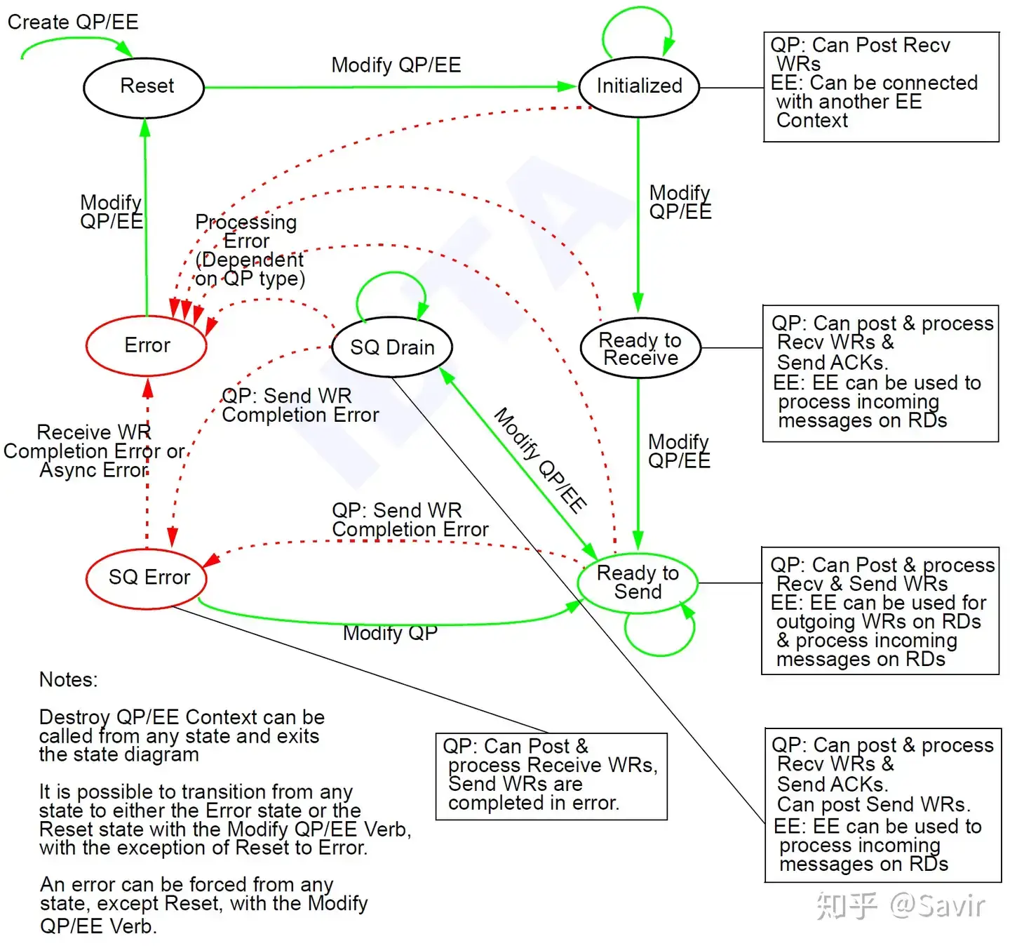
Speaking of the state of QP, we have to bring out the following image (taken from section 10.3.1 of the IB protocol):
QP State Machine
The so-called state machine describes the different states of an object and the conditions that trigger transitions between states. Designing a state machine for an object can make the lifecycle of this object very clear, and in implementation, it will also make the logic more coherent.
For QP, the IB specification also designs several states for it. The functions of a QP in different states vary. For example, only after entering the Ready to Send state can the QP perform Post Send data operations. State transitions between normal states (in green) are actively triggered by the user through the Modify QP user interface introduced above; whereas error states (in red) often automatically transition after an error occurs. When a QP is in an error state, it cannot perform normal operations and needs to be reconfigured to a normal state by the upper layer through Modify QP.
In the above diagram, we only focus on the part of QP. EE (End-to-End Context) is a concept specifically used for RD service types, which we will not cover for now. We enter this state diagram through the Create QP interface and exit this state diagram through the Destroy QP interface.
QP has the following states, we will only introduce some important points:
# RST (Reset)
Reset state. When a QP is created through Create QP, it is in this state. The related resources have already been allocated, but this QP cannot do anything at the moment. It cannot receive WQEs issued by the user, nor can it receive messages from a QP on the peer end.
# INIT(Initialized)
Initialized state. In this state, the user can issue Receive WR to this QP via Post Receive, but the received messages will not be processed and will be silently discarded; if the user issues a Post Send WR, an error will occur.
# RTR(Ready to Receive)
Ready to receive status. Based on the INIT state, RQ can function normally, meaning it can move data to the specified memory location according to the instructions in the received message’s WQE. In this state, SQ still cannot function.
# RTS (Ready to Send)
Ready to send status. Based on RTR, SQ can work normally, meaning the user can perform Post Send, and the hardware will also send the data according to the content of SQ. Before entering this state, QP must have already established a connection with the peer.
# SQD (Send Queue Drain)
SQ emptying state. As the name suggests, this state will process all the existing unprocessed WQEs in the SQ queue. At this time, the user can still submit new WQEs, but these WQEs will be processed only after all the old WQEs have been processed.
# SQEr (Send Queue Error)
SQ error state. When a Send WR encounters a completion error (i.e., an error reported to the driver by the hardware through CQE), it causes the QP to enter this state.
# ERR (Error)
Error state. If an error occurs in other states, they may enter this state. In the Error state, the QP will stop processing WQE, and any WQE that is halfway processed will also stop. The upper layer needs to switch the QP back to the initial RST state after fixing the error.
# Summary
This article first reviews some important basic concepts of QP, then explains QPC, QPN, and other concepts closely related to QP, and finally introduces the interfaces commonly used by users to operate QP and the QP state machine. I believe that after reading this article, readers will have a deeper understanding of QP.
In fact, as a core concept of RDMA, there is a lot of content regarding QP, and this article cannot cover everything. I will gradually complete the related content in future articles. For example, the concept of QKey will be explained in detail in subsequent articles dedicated to various Keys.
Alright, this is the end of the article. Thank you for reading. A preview of the next article will provide a detailed explanation of CQ.
# Relevant sections of the agreement
3.5.1 10.2.4 Basic Concepts of QP
10.3 QP State Machine
10.2.5 Software interfaces related to QP
11.4 Post Send Post Recv