
This article welcomes non-commercial reproduction, please indicate the source when reproducing.
Statement: For collection only, for easy reading
― Savir, Zhihu Column: 7. RDMA and Protection Domain
In the previous text, we briefly introduced some of the most common resources in RDMA, including various Queues and the concept of MR, among others. MR is used to control and manage HCA’s access rights to local and remote memory, ensuring that the HCA can only read and write to memory regions that the user has registered after obtaining the correct Key. To better ensure security, the IB protocol also introduced the concept of Protection Domain (PD) to ensure mutual isolation among RDMA resources. This article will introduce the concept of PD.
# What is PD?
PD stands for Protection Domain. The concept of a domain is often seen, from mathematical “real number fields” and “complex number fields” to geographical “airspace” and “sea area,” representing a space/range. In RDMA, a PD is like a “container” that holds various resources (QP, MR, etc.), bringing these resources under its protection to prevent unauthorized access. Multiple protection domains can be defined within a node, and the resources contained within each PD are isolated from each other and cannot be used together.
The concept is still somewhat abstract, let’s take a look at what role PD plays and what specific problems it solves.
# The function of PD
A user may create multiple QPs and multiple MRs, and each QP may establish connections with different remote QPs, as shown in the diagram below (gray arrows indicate the connection relationships between QPs):
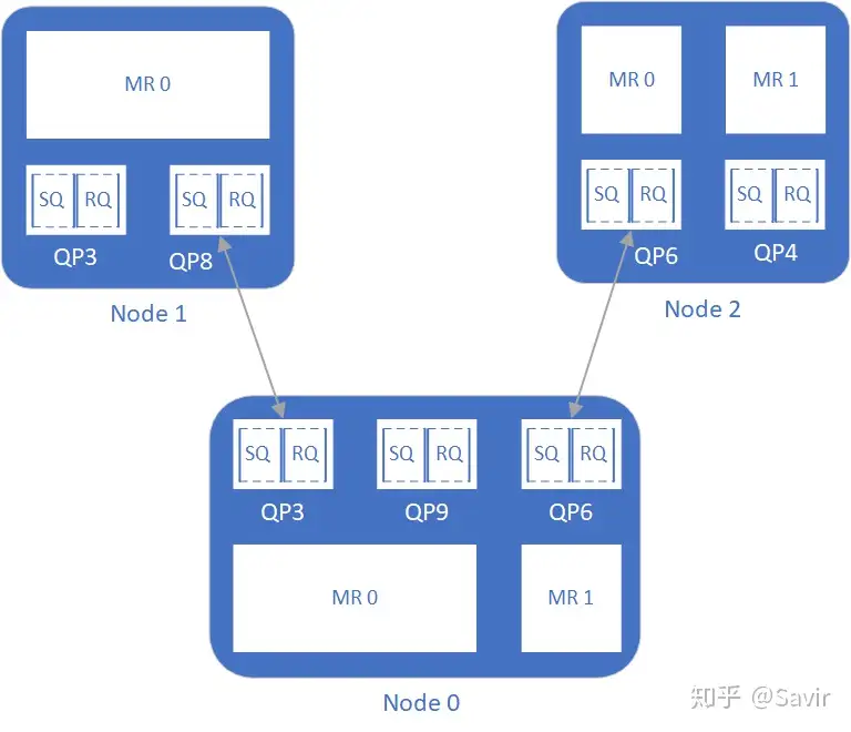
Figure 1: RDMA Resources Without PD Concept
Since there is no binding relationship between MR and QP, this means that once a remote QP establishes a connection with a local QP and the conditions for communication are met, theoretically, as long as the remote node knows the VA and R_key (it can even keep guessing until it gets a valid pair of values), it can access the contents of an MR on the local node.
In general, the virtual address VA of MR and the key R_Key are difficult to guess, which already ensures a certain level of security. However, to better protect the data in memory and further isolate and divide the permissions of various resources, we have defined PD in each node, as shown in the diagram below.
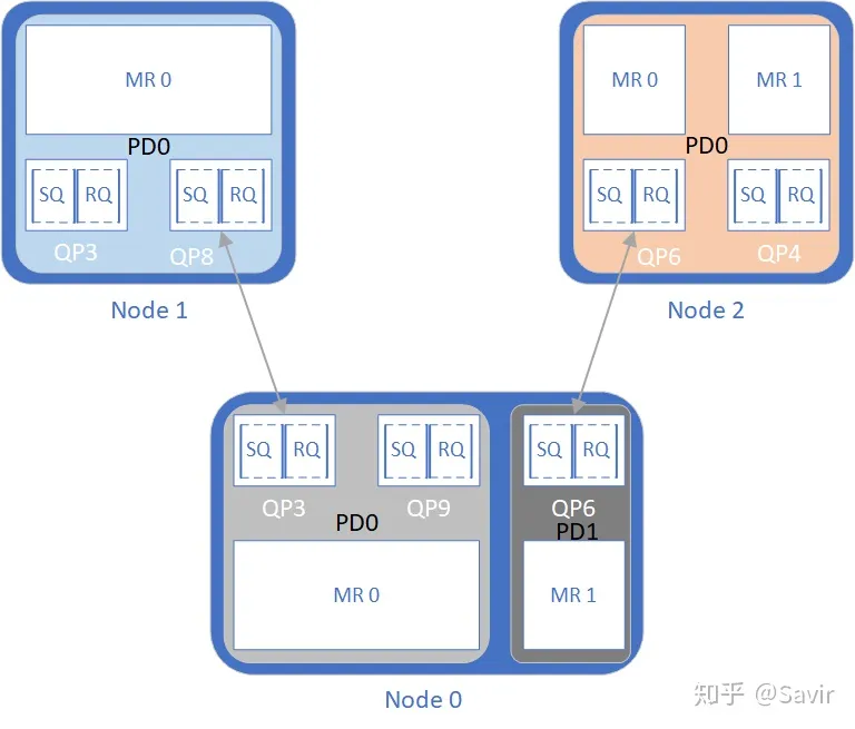
Figure 2: RDMA resources when adding the PD concept
In the diagram, Node 0 has two PDs, with 3 QPs and 2 MRs divided into two groups. Additionally, Node 1 and Node 2 each have a PD containing all QPs and MRs. The resources in the two PDs on Node 0 cannot be used together, meaning QP3 and QP9 cannot access the data of MR1, and QP6 cannot access the data of MR0. If we specify the hardware to use QP3 and MR1 during data transmission, the hardware will verify that they do not belong to the same PD and return an error.
For the remote node, Node1 can only access Node0’s memory through QP3 connected via QP8. However, because Node0’s QP3 is “encircled” in the protection domain PD0, Node1’s QP8 can only access the memory corresponding to MR0, and cannot access the data in MR1 under any circumstances. This is restricted from two aspects:
- Node 1’s QP8 is only connected to Node 0’s QP3, and cannot access memory through Node 0’s QP6.
- MR1 and QP3 of Node 0 belong to different PDs, so even if QP8 of Node 1 obtains the VA and R_key of MR1, the hardware will refuse to provide service due to different PDs.
As mentioned at the beginning of this article, a PD is like a container that protects some RDMA resources, isolating them from each other to enhance security. In fact, RDMA includes not only resources like QP and MR, but also Address Handle, Memory Window, etc., which are also isolated and protected by PD, as will be introduced later.
# How to use PD
Still looking at the above diagram, we notice that Node 0 has two PDs for resource isolation, whereas Node 1 and Node 2 have only one PD containing all the resources.
The reason I draw it this way is to illustrate that the number of PDs divided on a node is entirely up to the user. If you want to enhance security, then each QP connected to a remote node and the MR provided for remote access should be isolated as much as possible by dividing PDs. If higher security is not a concern, then creating one PD that encompasses all resources is also acceptable.
The IB protocol specifies: Each node must have at least one PD, each QP must belong to a PD, and each MR must also belong to a PD.
So how is the inclusion relationship of PD reflected in the software? It itself has a software entity (structure) that records some information about this protection domain. Before users create resources like QP and MR, they must first create a PD through the interface of the IB framework to get its pointer/handle. Then, when creating QP and MR, this PD’s pointer/handle needs to be passed in, and PD information will be included in QP and MR. When the hardware sends and receives packets, it will verify the PD of QP and MR. I will introduce more about the software protocol stack in later articles.
Additionally, it is important to emphasize that PD is a local concept and only exists within the node, it is not visible to other nodes; whereas MR is visible to both the local and remote ends.
For everyone’s convenience in referencing and learning, I will list the protocol sections involved in the articles. I will also supplement the previous content when I have time.
# PD related protocol chapter
- Basic concepts and functions of 3.5.5 PD
- 10.2.3 introduces the relationship between PD and some other RDMA resources, as well as the software interfaces related to PD.
- 10.6.3.5 Emphasize again the relationship between PD, MR, and QP.
- 11.2.1.5 Detailed introduction to the Verbs interface of PD, including functions, input parameters, output parameters, and return values, etc.
Alright, that concludes the introduction to PD. In the following text, I will introduce the concept of Address Handle used for UD service types.