
This article welcomes non-commercial reprints, please indicate the source when reprinting.
Statement: For collection purposes only, for easier reading
― Savir, Zhihu Column: 4. RDMA Operation Types
In previous articles discussing RDMA communication processes, SEND-RECV has been mentioned frequently. However, it cannot really be called “RDMA”; it is merely an “upgraded version” of the traditional send-receive model with added zero-copy and protocol stack offloading. This type of operation does not fully leverage the entire capabilities of RDMA technology and is often used in scenarios where control information is exchanged between two ends. When it comes to sending and receiving large amounts of data, two RDMA-exclusive operations are more commonly used: WRITE and READ.
Let’s first review the dual-end operations—SEND and RECV, and then introduce and compare the single-end operations—WRITE and READ.
# SEND & RECV
SEND and RECV are two different types of operations, but because if one end performs a SEND operation, the opposite end must perform a RECV operation, they are usually described together.
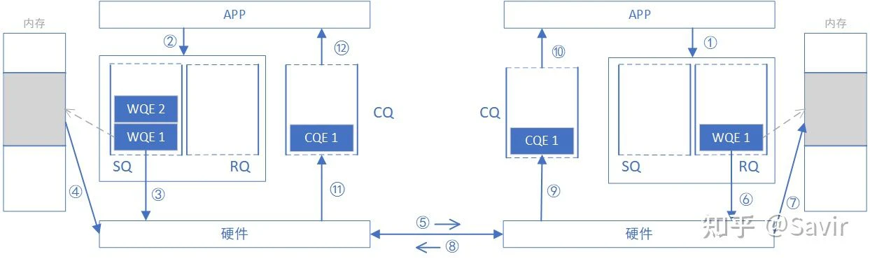
Why is it called “dual-end operation”? Because completing a communication process requires the participation of both ends’ CPUs, and the receiving end needs to explicitly issue a WQE in advance. The diagram below is a schematic of a SEND-RECV operation process. The original image is from [1], and I have made some modifications.

In the previous section, we discussed how upper-layer applications issue tasks to hardware through WQE (WR). In SEND-RECV operations, not only does the sender need to issue WQE, but the receiver also needs to issue WQE to inform the hardware where to place the received data. The sender does not know where the sent data will be placed, so each time data is sent, the receiver must prepare the receive buffer in advance, and the receiver’s CPU will naturally be aware of this process.
In order to compare the similarities and differences between SEND/RECV and WRITE/READ in the following text, we will supplement the memory read and write process in the SEND-RECV flow from the previous article, namely steps ④ in the diagram below — the sending-end hardware retrieves data from memory based on the WQE and encapsulates it into packets that can be transmitted on the link, and step ⑦ — the receiving-end hardware parses the packets and places the data into the specified memory area based on the WQE. Other steps will not be elaborated. Additionally, it is emphasized once again that the order of steps on the sending and receiving ends may not necessarily follow the order in the diagram. For example, the order of steps ⑧⑪⑫ and steps ⑨⑩ is not fixed.
The following will introduce the WRITE operation, and I believe everyone can understand it better after comparison.
# WRITE
WRITE is the full name of the RDMA WRITE operation, which is the behavior of actively writing to remote memory from the local end. Except for the preparation phase, the remote CPU does not need to participate and is not aware of when data is written or when the data reception is complete. Therefore, this is a single-end operation.
Through the diagram below, we compare the differences between WRITE and SEND-RECV operations. In the preparation phase, this end obtains the address and “key” of a certain piece of available memory on the opposite end through data exchange, which is equivalent to obtaining read and write permissions for this piece of remote memory. After obtaining the permissions, this end can directly read and write to this remote memory area as if accessing its own memory, which is the essence of RDMA—Remote Direct Memory Access.
How are the destination address and key obtained in WRITE/READ operations? They can usually be obtained through the SEND-RECV operation we just discussed, because obtaining the key is ultimately allowed by the controller of the remote memory—the CPU. Although the preparation work is relatively complex, once the preparation is completed, RDMA can leverage its advantages to read and write large amounts of data. Once the remote CPU authorizes the memory for local use, it will no longer participate in the data transmission process, which frees the remote CPU and reduces communication latency.
It should be noted that this end reads and writes remote memory through virtual addresses, making it very convenient for upper-layer applications to operate on it. The actual conversion of virtual addresses to physical addresses is performed by the RDMA network card. How this conversion is done will be introduced in subsequent articles.
Ignoring the process of obtaining the key and addr during the preparation phase, we describe the process of a WRITE operation below. From now on, we will no longer refer to the local and remote ends as “sending” and “receiving” ends, but rather as “request” and “response” ends. This makes it more appropriate for describing both WRITE and READ operations and avoids ambiguity.
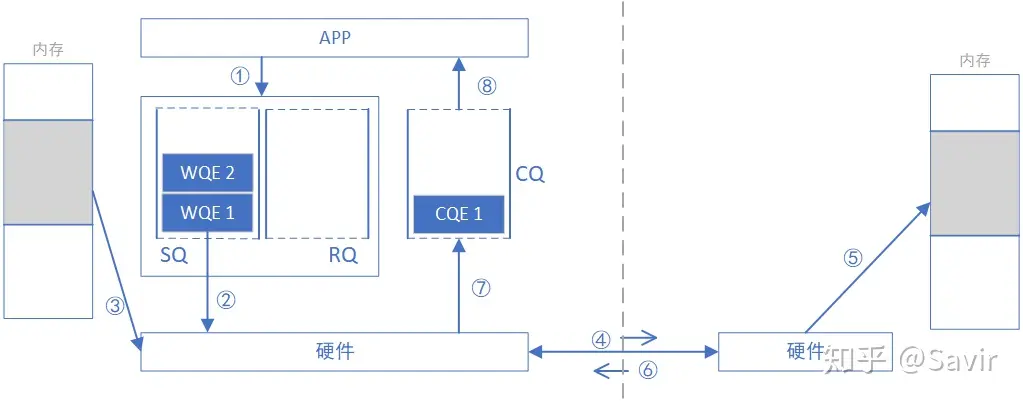
- The requesting APP issues a WRITE task in the form of WQE (WR).
- Requesting hardware to fetch WQE from SQ and parse the information.
- The requester’s network card converts the virtual address in the WQE to obtain the physical address, then retrieves the data to be sent from memory, and assembles the data packet.
- The requesting end’s network card sends the data packet to the responding end’s network card through the physical link.
- The receiving end receives the data packet, parses the destination virtual address, converts it to a local physical address, parses the data, and places the data in the specified memory area.
- The responding end replies with an ACK message to the requesting end.
- After the network card on the requesting side receives the ACK, it generates a CQE and places it into the CQ.
- The requesting app obtains task completion information.
Note: Strictly speaking, at step 6 when ACK is replied, the RDMA network card can only guarantee that the Payload in the packet has been “temporarily stored,” but it cannot guarantee that the data has been placed in the destination memory. However, this does not affect our understanding of the sorting process. Thanks to @nekomii for the reminder.
IB Spec. 9.7.5.1.6 ACKNOWLEDGE MESSAGE SCHEDULING Original text: “For SEND or RDMA WRITE requests, an ACK may be scheduled before data is actually written into the responder’s memory. The ACK simply indicates that the data has successfully reached the fault domain of the responding node. That is, the data has been received by the channel adapter and the channel adapter will write that data to the memory system of the responding node, or the responding application will at least be informed of the failure.”
# READ
As the name suggests, READ and WRITE are opposite processes, with READ being the local end actively reading the remote memory. Like WRITE, the remote CPU does not need to participate and is not aware of the process of data being read from memory.
The process of obtaining the key and virtual address is no different from WRITE. It is important to note that the data requested by the “read” action is carried in the message replied by the other end.
The following describes the process of a READ operation, note that it only differs from WRITE in direction and order of steps.
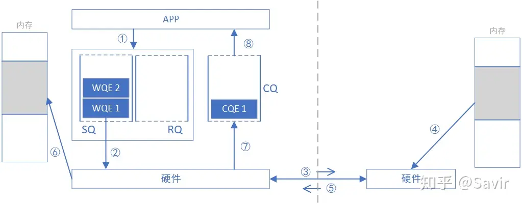
- The requesting end APP issues a READ task in the form of WQE.
- The requesting network card retrieves the WQE from the SQ and parses the information.
- The requesting network card sends the READ request packet to the responding network card through the physical link.
- The receiving end receives the data packet, parses the destination virtual address, converts it into a local physical address, parses the data, and retrieves the data from the specified memory area.
- The receiving end hardware assembles the data into a reply packet and sends it to the physical link.
- The requesting hardware receives the data packet, parses and extracts the data, and then places it in the memory area specified by the READ WQE.
- The requester’s network card generates a CQE and places it in the CQ.
- The requesting APP obtains task completion information.
# Summary
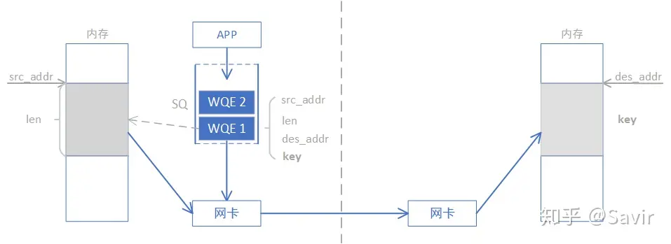
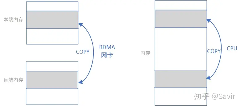
We abstract by ignoring various details, and RDMA WRITE and READ operations are simply utilizing the network card to complete the memory copy operation shown in the left diagram below. The copying process is completed by the RDMA network card through the network link; whereas local memory copying, as shown in the right diagram below, is completed by the CPU through the bus:
The words used in the RDMA standard to define the aforementioned operations are very appropriate, “receive” and “send” have the semantics of requiring active participation from the peer, while “read” and “write” are more like the semantics of the local end operating on a passive peer.
By comparing SEND/RECV and WRITE/READ operations, we can find that WRITE/READ, which does not require the responding end’s CPU involvement during data transmission, has greater advantages. The drawback is that the requesting end needs to obtain read and write permissions for a section of memory on the responding end during the preparation phase. However, during actual data transmission, the power and time consumption of this preparation phase can be negligible. Therefore, RDMA WRITE/READ is the type of operation used for large data transfers, while SEND/RECV is usually used to transmit some control information.
In addition to the types of operations introduced in this article, there are more complex types of operations such as ATOMIC, which will be analyzed in detail in the protocol interpretation section later. This concludes this article, and the next one will introduce the basic service types of RDMA.
# Code example
The operation types in this text are all issued through WQE. Below is a simple example demonstrating how to use libibverbs to create a QP and then issue a WRITE operation through WQE.
| |
# References
[1] part1-OFA_Training_Sept_2016.pdf