
This article welcomes non-commercial reprints, please indicate the source.
Statement: For collection only, for easy reading
― Savir, Zhihu Column: 3. Basic Elements of RDMA
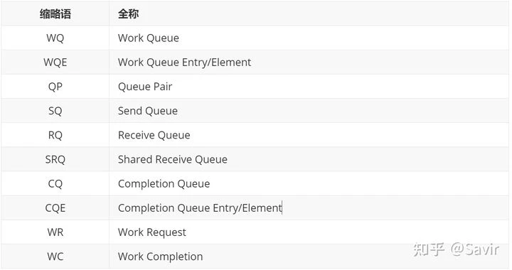
In RDMA technology, abbreviations are often used, which can easily confuse newcomers. The purpose of this article is to explain the most basic elements in RDMA and their meanings.
I will write a table of common abbreviations at the front, so if you forget while reading, you can refer to it at the front.
# WQ
Work Queue, abbreviated as WQ, is one of the most important concepts in RDMA technology. WQ is a queue that stores work requests. To clearly explain what WQ is, we first introduce the elements in this queue, WQE (Work Queue Element).
# WQE
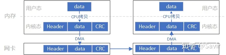
WQE can be considered a “task description,” which is a work request issued by software to hardware. This description contains the tasks that the software hopes the hardware will perform, as well as detailed information about the task. For example, a task might be like this: “I want to send data located at address 0x12345678 with a length of 10 bytes to the opposite node.” After receiving the task, the hardware will use DMA to fetch the data from memory, assemble the data packet, and then send it.
The meaning of WQE should be quite clear, so what is the WQ we mentioned at the beginning? It is the “folder” used to store “task documents,” and the WQ can contain many WQEs. Readers with a basic understanding of data structures should know that a queue is a first-in-first-out data structure, which is very common in computer systems. We can use the diagram below to represent the relationship between WQ and WQE described above:
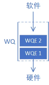
WQ This queue is always added to by the software with WQE (enqueue), and the hardware extracts WQE from it, which is the process of the software “issuing tasks” to the hardware. Why use a queue instead of a stack? Because the “store” and “retrieve” operations are performed separately by software and hardware, and it is necessary to ensure that user requests are processed in order. In RDMA technology, all communication requests must be notified to the hardware in the manner shown in the above diagram, which is often referred to as “Post”.
# QP
Queue Pair, abbreviated as QP, means “a pair” of WQ.
# SQ and RQ
Any communication process must have both sending and receiving ends. A QP is a combination of a send work queue and a receive work queue, which are referred to as the SQ (Send Queue) and RQ (Receive Queue) respectively. Let’s enrich the diagram above; the left side is the sending end, and the right side is the receiving end:
Why is WQ missing? SQ and RQ are both WQ, WQ just represents a unit that can store WQE, SQ and RQ are the instances.
SQ is specifically used to store send tasks, and RQ is specifically used to store receive tasks. In a SEND-RECV process, the sender needs to place a WQE representing a send task into the SQ. Similarly, the receiver software needs to issue a WQE representing a receive task to the hardware so that the hardware knows where to place the received data in memory. The Post operation we mentioned earlier is called Post Send for SQ and Post Receive for RQ.
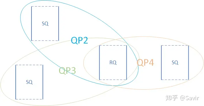
It should be noted that in RDMA technology, the basic unit of communication is QP, not the node. As shown in the figure below, for each node, each process can use several QPs, and each local QP can be “associated” with a remote QP. Saying “Node A sends data to Node B” is not sufficient to fully describe an RDMA communication; it should be more like “QP3 on Node A sends data to QP4 on Node C.”
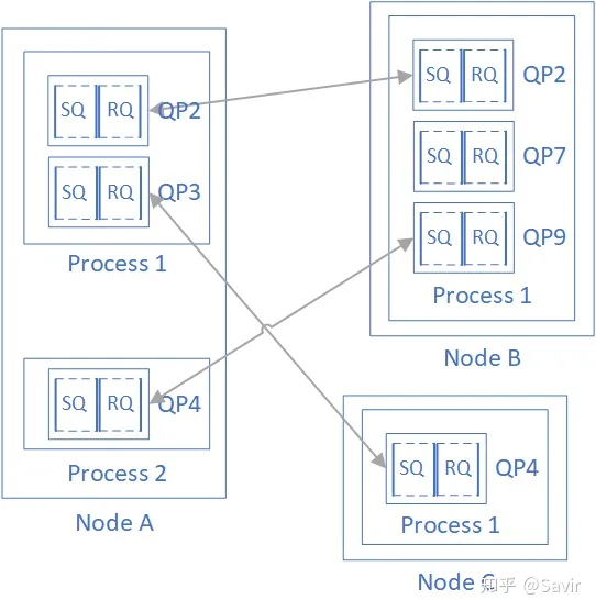
Each QP of every node has a unique number, called QPN (Queue Pair Number), which can uniquely identify a QP on a node.
# SRQ
Shared Receive Queue, abbreviated as SRQ, means a shared receive queue. The concept is easy to understand; it refers to a situation where several QPs share the same RQ, which we call SRQ. We will later learn that the use of RQ is far less than the use of SQ, and each queue consumes memory resources. When we need to use a large number of QPs, we can save memory through SRQ. As shown in the figure below, QP2~QP4 use the same RQ together:
# CQ
Completion Queue, abbreviated as CQ, means completion queue. Similar to WQ, we first introduce the elements in the CQ queue — CQE (Completion Queue Element). CQE can be considered the opposite concept of WQE. If WQE is the “task list” issued by software to hardware, then CQE is the “task report” returned by hardware to software after completing the task. CQE describes whether a task was executed correctly or if an error was encountered, and if so, what the cause of the error was.
And CQ is the container that carries CQE—a first-in-first-out queue. If we invert the diagram representing the relationship between WQ and WQE, we get the relationship between CQ and CQE:
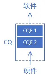
Each CQE contains completion information for a certain WQE, and their relationship is shown in the diagram below:

Below, we put CQ and WQ (QP) together to see the interaction between software and hardware in a single SEND-RECV operation (the order of numbers in the diagram does not represent the actual sequence):
2022/5/23: The order of the diagram and the subsequent list has been modified. The original item 2 “The receiving end hardware takes the task book from the RQ and prepares to receive data” has been moved to after “The receiving end receives data, verifies it, and then sends an ACK message back to the sender,” and the description has been modified. It is now item 6.
The mistake I made here is that RQ and SQ are different; RQ is a “passive reception” process, and the hardware only consumes RQ WQE when it receives a Send packet (or a Write packet with an immediate value). Thanks to @连接改变世界 for the correction.
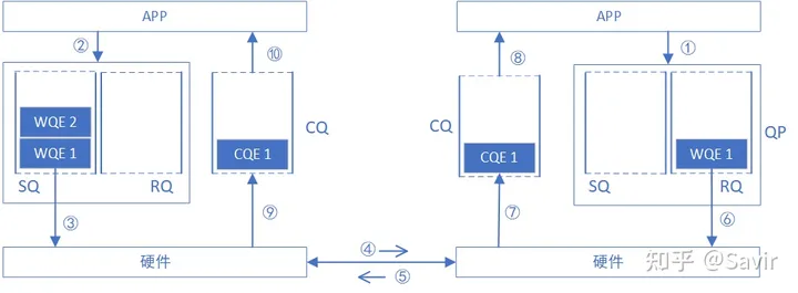
- The receiving end APP issues a RECV task to the RQ in the form of WQE.
- The sending-end APP issues a SEND task to the SQ in the form of a WQE.
- The sending-end hardware retrieves the task list from the SQ, obtains the data to be sent from memory, and assembles the data packet.
- The sender’s network card sends the data packet to the receiver’s network card through the physical link.
- After the receiving end receives the data and verifies it, it sends an ACK message back to the sending end.
- The receiving-end hardware takes a work queue entry (WQE) from the RQ.
- The receiving end hardware places the data in the location specified by the WQE, then generates a “task report” CQE, and places it in the CQ.
- The receiving end APP obtains task completion information.
- After the network card at the sending end receives the ACK, it generates a CQE and places it into the CQ.
- The sending-end APP obtains task completion information.
Note
NOTE: One important point to note is that the example in the above diagram is the interaction flow of a reliable service type. If it is an unreliable service, there will be no ACK reply in step 5, and step 9 and subsequent steps will be triggered immediately after step 5. We will explain service types and the difference between reliable and unreliable in the article “Basic RDMA Service Types.”
At this point, through the two media, WQ and CQ, both ends of the software and hardware have jointly completed a transmission and reception process.
# WR and WC
After discussing several Queues, there are actually two concepts mentioned at the beginning of the article that have not been explained, namely WR and WC (not the abbreviation for Water Closet).
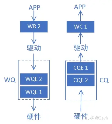
WR stands for Work Request; WC stands for Work Completion. These two are actually “mappings” of WQE and CQE at the user level. Since the APP completes RDMA communication by calling the protocol stack interface, WQE and CQE themselves are not visible to the user and are concepts within the driver. What the user actually submits through the API is WR, and what is received is WC.
WR/WC and WQE/CQE are the same concepts at different levels of entities, both being “task book” and “task report”. Therefore, we have added some content to the two diagrams mentioned earlier:
# Code example
Finally, below is a simple example demonstrating how to use libibverbs to create a QP and then send data through this QP. This is a very simple example, just to give readers an intuitive understanding of the concepts mentioned above.
| |
# Summary
Alright, let’s use Figure 11 from section 3.2.1 of the IB protocol[1] to summarize the content of this article:
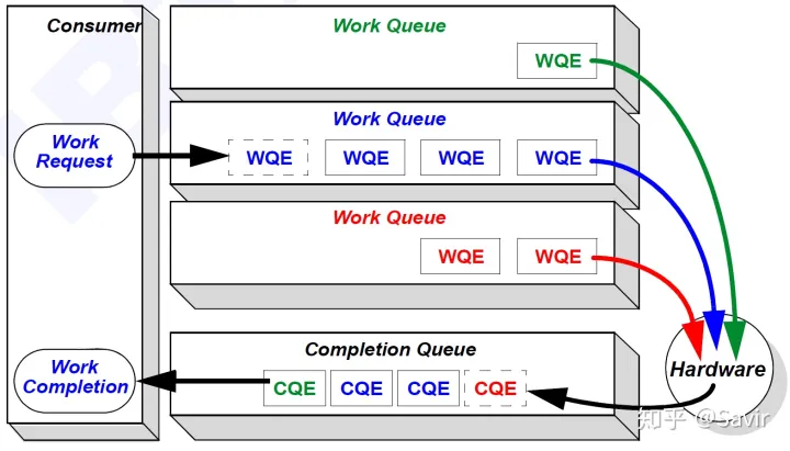
The user-mode WR is converted by the driver into a WQE and filled into the WQ. The WQ can be an SQ responsible for sending or an RQ responsible for receiving. The hardware will take out the WQE from each WQ and complete the sending or receiving task according to the requirements in the WQE. After the task is completed, a CQE will be generated for this task and filled into the CQ. The driver will take out the CQE from the CQ and convert it into a WC to return to the user.
The introduction to the basic concepts ends here. The next article will introduce several common types of RDMA operations.
# References
[1] “IB Specification Vol 1-Release-1.3-2015-03-03”