
This article welcomes non-commercial reproduction, please indicate the source.
Statement: For collection only, for easy reading
― Savir, Zhihu Column: 10. RDMA Completion Queue
We have briefly introduced CQ in previous articles, and this article will delve deeper into some of its details. Before reading this article, readers can first review this article: 【“3. RDMA Basic Elements”】 .
# Basic Concepts
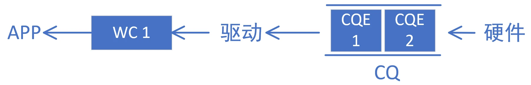
Let’s first review the function of CQ. CQ stands for Completion Queue, and its function is opposite to that of WQ (SQ and RQ). The hardware uses CQE/WC in the CQ to inform the software about the completion status of a certain WQE/WR. A reminder to readers: for upper-layer users, WC is generally used, while for drivers, it is generally referred to as CQE. This article does not distinguish between the two.
CQE can be regarded as a “report” that specifies the execution status of a certain task, including:
- Which task specified by which WQE of which QP was completed this time (QP Number and WR ID)
- What operation was performed in this task (Opcode operation type)
- This task executed successfully/failed, the reason for failure is XXX (Status and error code)
- …
Whenever the hardware completes processing a WQE, a CQE is generated and placed in the CQ queue. If a CQE corresponding to a WQE is not generated, then this WQE will always be considered as not yet processed. What does this mean?
- Operations involving fetching data from memory (SEND and WRITE)
Before generating a CQE, the hardware may not have sent the message yet, may be in the process of sending the message, or the peer may have received the correct message. Since the memory region is allocated before sending, the upper-level software must consider this memory region still in use before receiving the corresponding CQE and cannot release all related memory resources.
- Operations involving storing data in memory (RECV and READ)
Before the CQE is generated, it is possible that the hardware has not started writing data, it is possible that only half of the data has been written, or it is possible that a data verification error has occurred. Therefore, before the upper-layer software receives the CQE, the contents of the memory area used to store the received data are unreliable.
In summary, the user must obtain the CQE and confirm its content before considering the message sending and receiving task complete.
# When was it generated?
We will explain separately according to the service type (this article only discusses RC and UD) and the operation type, because the timing and meaning of generating CQE are different in different situations. Readers are advised to review the 4th article “4. Basic RDMA Operations” and the 5th article “5. Basic RDMA Service Types” .
- Reliable Service Type (RC)
The previous article mentioned that reliability means that the sender is concerned that the message sent can be accurately received by the receiver, which is ensured through mechanisms such as ACK, checksum, and retransmission.
- SEND
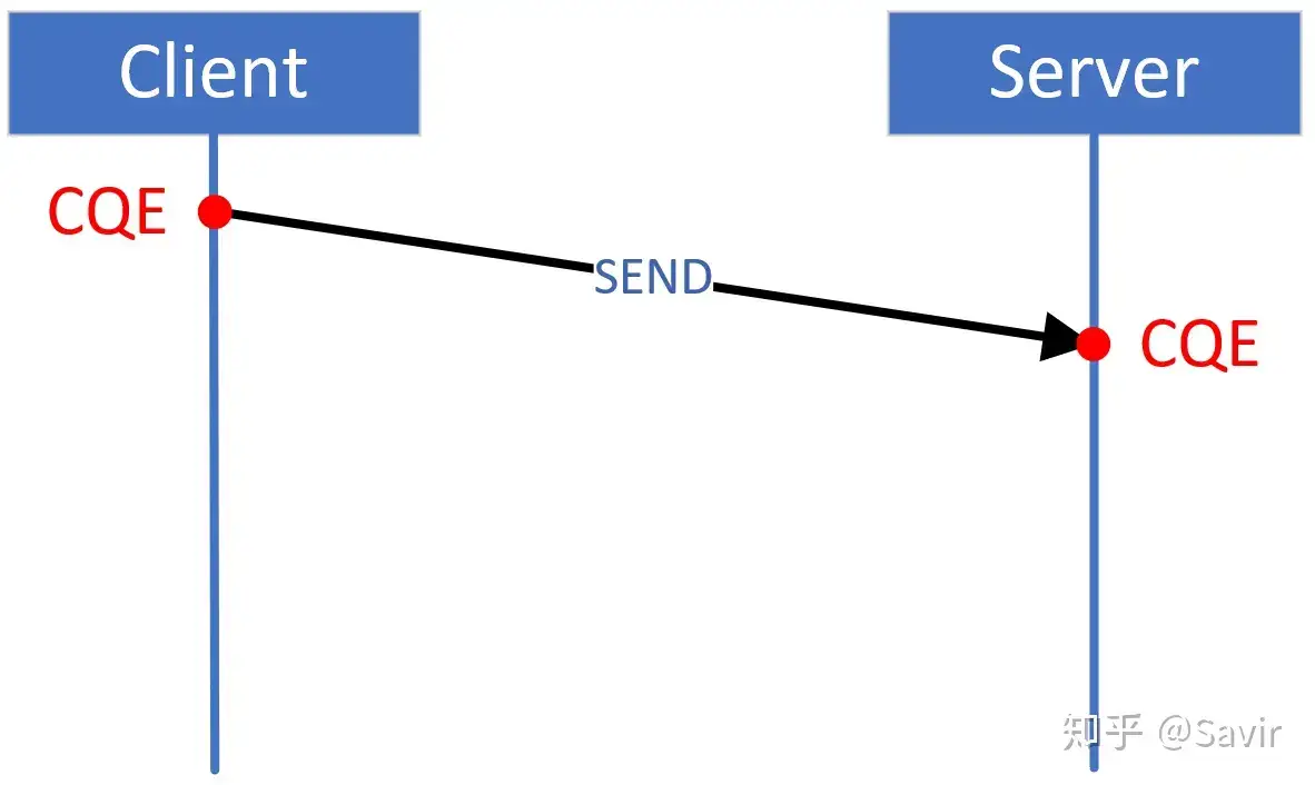
SEND operation requires hardware to fetch data from memory, then assemble it into packets to send to the other end through a physical link. For SEND, the Client side generates a CQE indicating the other end has received the data accurately, after the other end’s hardware receives and verifies the data, it will reply with an ACK packet to the sender. Only after the sender receives this ACK will a CQE be generated, thus informing the user that the task has been successfully executed. As shown in the figure, the left Client side generates the CQE for this task at the position marked by the red dot.
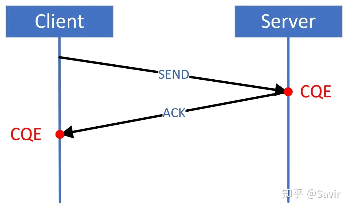
- RECV
The RECV operation requires the hardware to place the received data into the memory area specified in the user’s WQE. After completing the checksum and data storage actions, the hardware will generate a CQE, as shown on the right side of the above figure on the server side.
- WRITE
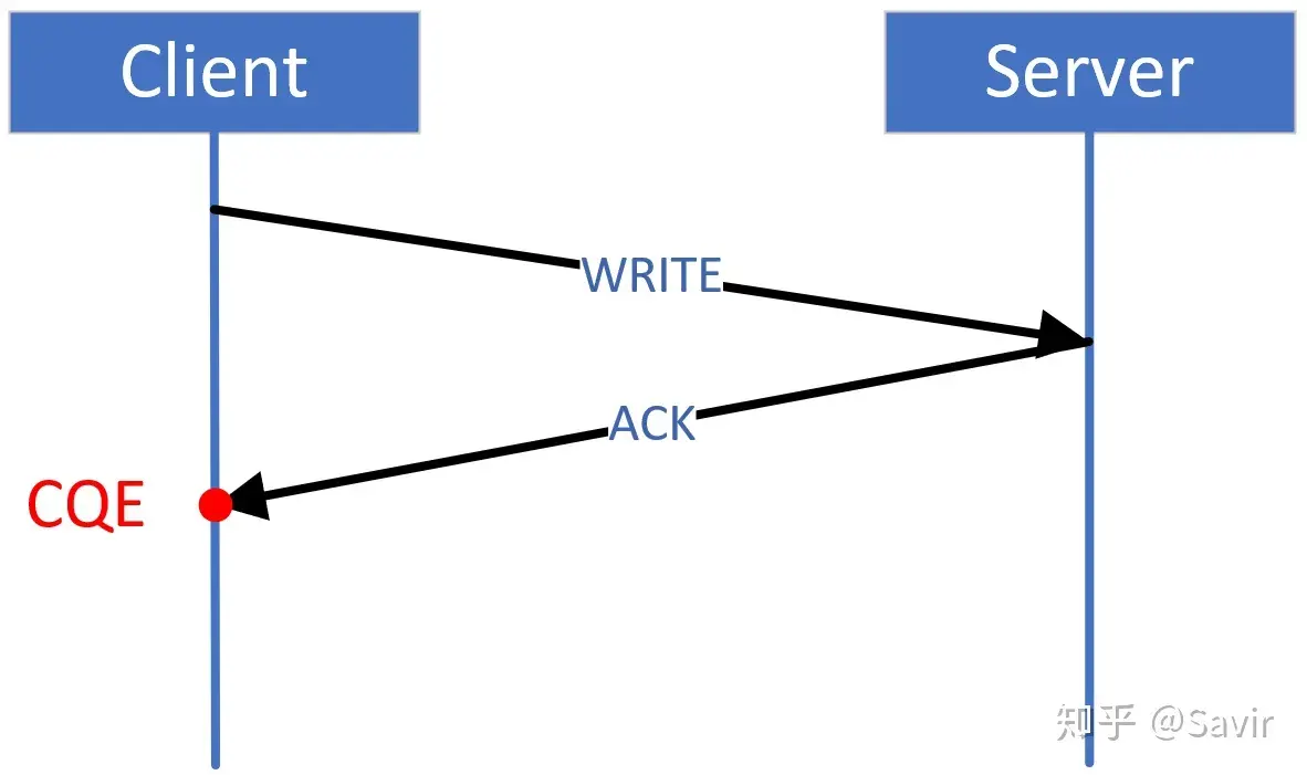
For the Client side, WRITE operation and SEND operation are the same, the hardware will fetch data from memory and wait for the peer to reply with an ACK before generating a CQE. The difference is that because WRITE is an RDMA operation, the peer CPU is not aware of it, and naturally the user is not aware of it either, so the diagram above becomes like this:
- READ
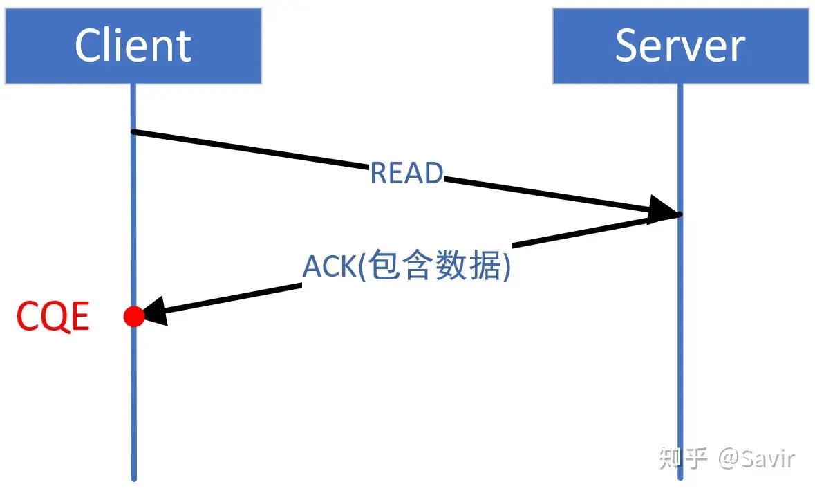
READ and RECV are somewhat similar. After the Client initiates a READ operation, the other side will reply with the data we want to read. Then, after verifying that there are no issues, the data will be placed in the specified location in the WQE. After completing the above actions, a CQE will be generated on our side. READ is also an RDMA operation, which is not perceived by the other side’s user, and naturally, no CQE is generated. In this situation, the diagram becomes like this:
- Unreliable Service Type (UD)
Because unreliable service types lack retransmission and acknowledgment mechanisms, generating a CQE indicates that the hardware has already sent out the data specified by the corresponding WQE. It was previously mentioned that UD only supports SEND-RECV operations and does not support RDMA operations. Therefore, for both ends of the UD service, the timing for CQE generation is as shown in the figure below:
# The correspondence between WQ and CQ
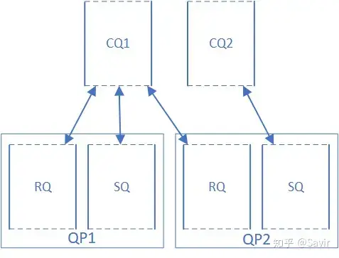
Each WQ must be associated with a CQ, and each CQ can be associated with multiple SQs and RQs.
The so-called “association” here refers to the fact that all CQEs corresponding to a WQ’s WQEs will be placed by the hardware into the bound CQ. It’s important to note that the SQ and RQ belonging to the same QP can each be associated with different CQs. As shown in the diagram below, both the SQ and RQ of QP1 are associated with CQ1, while the RQ of QP2 is associated with CQ1 and the SQ is associated with CQ2.
Because each WQ must be associated with a CQ, the user needs to create the CQ in advance before creating the QP, and then specify which CQ will be used by the SQ and RQ respectively.
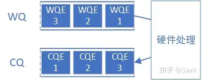
The WQEs in the same WQ correspond to CQEs that are ordered
The hardware retrieves WQEs from a certain WQ (SQ or RQ) and processes them in a “First In, First Out” FIFO order, and when placing CQEs in the CQ associated with WRs, it also follows the order in which these WQEs were placed in the WQ. Simply put, whoever is placed in the queue first is completed first. This process is shown in the diagram below:
It should be noted that the use of SRQ and the RQ in RD service type are both non-order-preserving, which will not be discussed in this article.
The WQEs in different WQs are not ordered with respect to their corresponding CQEs.
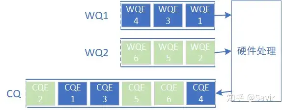
In the previous text, we mentioned that a CQ might be shared by multiple WQs. In this case, the order of generation for the CQEs corresponding to these WQEs cannot be guaranteed. As shown in the figure below (the WQE number indicates the order of issuance, i.e., 1 is issued first, and 6 is issued last):
The above description actually also includes the situation of “WQE in SQ and RQ of the same QP, their corresponding CQE is not ordered.” This is actually quite easy to understand. SQ and RQ, one is responsible for actively initiating tasks, and the other for passively receiving tasks. They can be considered as channels in two different directions and naturally should not affect each other. Suppose the user first issues a Receive WQE and then a Send WQE for the same QP. It can’t be that if the peer doesn’t send a message to the local end, the local end cannot send a message to the peer, right?
In this case, since the order in which CQEs are generated is not related to the order in which WQEs are obtained, how do the upper-level application and driver know which WQE the received CQE is associated with? It’s actually quite simple, the CQE indicates the number of the WQE it corresponds to.
Additionally, it should be noted that even when multiple WQs share a single CQ, “WQEs in the same WQ have their corresponding CQEs ordered” is always guaranteed. This means that the CQEs corresponding to WQE 1, 3, and 4 belonging to WQ1 in the above diagram are generated in sequence, and the same applies to WQE 2, 5, and 6 belonging to WQ2.
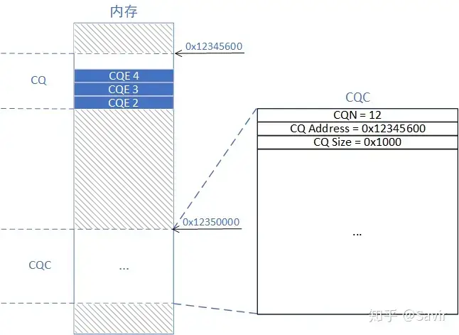
# CQC
Just like QP, CQ is merely a queue memory space for storing CQEs. Apart from knowing the starting address, the hardware is essentially unaware of this area. Therefore, it is necessary to agree on a format with the software in advance, and then the driver will allocate memory and fill in the basic information of the CQ in this memory according to the format for the hardware to read. This memory is the CQC. The CQC contains information such as the capacity size of the CQ, the sequence number of the currently processed CQE, and so on. So by slightly modifying the QPC diagram, you can represent the relationship between CQC and CQ:
# CQN
CQ Number is the CQ’s identifier, used to distinguish different CQs. CQ does not have special reserved numbers like QP0 and QP1, which will not be further elaborated in this article.
# Complete error
There are three types of errors in the IB protocol: immediate error, Completion Error, and Asynchronous Errors.
Immediate error refers to “immediately stop the current operation and return an error to the upper-level user”; completion error refers to “return the error information to the upper-level user via CQE”; whereas asynchronous error refers to “report to the upper-level user through an interrupt event.” It might still be a bit abstract, so let’s give an example to illustrate under what circumstances these two types of errors might occur:
- The user passed an illegal opcode when sending a Post Send, for example, trying to use RDMA WRITE operation during UD.
Result: Immediate error generated (some manufacturers may generate a completion error in this situation)
Generally, in this situation, the driver will directly exit the post send process and return an error code to the upper-level user. Note that at this point, the WQE has not yet been issued to the hardware before returning.
- The user issued a WQE with the operation type SEND, but did not receive an ACK from the other party for a long time.
Result: Generation completed with error
Because the WQE has already reached the hardware, the hardware will generate the corresponding CQE, which contains error details of the timeout unresponse.
- Multiple WQEs were issued in user mode, so the hardware generated multiple CQEs, but the software did not retrieve the CQEs from the CQ, causing the CQ to overflow. Result: Generate asynchronous error
Because the software has not fetched the CQE, it naturally will not obtain information from the CQE. At this time, the IB framework will call the event handler function registered by the software to notify the user to handle the current error.
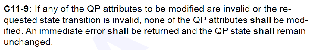
From this, it can be seen that they are all ways for the lower layer to report errors to the upper layer users, only the timing of their occurrence is different. In the IB protocol, it is specified which method should be used to report errors in different situations. For example, in the diagram below, for modifying illegal parameters during the Modify QP process, an immediate error should be returned.
The focus of this text is on CQ, so after introducing the error types, we will take a closer look at completion errors. Completion errors are reported by the hardware through filling error codes in the CQE. A communication process requires the participation of a requester and a responder, and the specific error causes are divided into local and remote. Let’s first take a look at the stage at which error detection is performed (the figure below is a redrawn version of Figure 118 in the IB protocol):
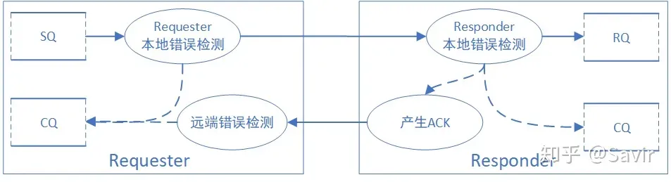
There are two error detection points for the Requester:
- Local error detection
Check the WQE in the SQ, if an error is detected, directly generate a CQE from the local error checking module to the CQ, and no data will be sent to the responder; if there is no error, send the data to the peer.
- Remote Error Detection
Detect whether the response side’s ACK is abnormal. ACK/NAK is generated by the peer’s local error detection module after detection, and it contains whether there is an error on the response side and the specific type of error. Regardless of whether there is an issue with the remote error detection result, a CQE will be generated in the CQ.
Responder’s error detection point is only one:
- Local error detection
In fact, what is detected is whether there is an issue with the peer message, which is also referred to as “local” error detection in the IB protocol. If an error is detected, it will be reflected in the ACK/NAK message sent back to the peer and will generate a CQE locally.
It should be noted that the generation of ACK and remote error detection mentioned above is only applicable to connection-oriented service types. Connectionless service types, such as UD type, do not care whether the peer receives it, and the receiver will not generate an ACK. Therefore, a CQE will definitely be generated after the local error detection of the Requester, regardless of whether there is a remote error.
Then we will briefly introduce several common completion errors:
- RC service type SQ completion error
- Local Protection Error
- Local protection domain error. The data memory address specified in the local WQE is invalid for the MR, meaning the user is attempting to use data from an unregistered memory region.
- Remote Access Error
- Remote permission error. The local end does not have permission to read/write the specified remote memory address.
- Transport Retry Counter Exceeded Error
- Retransmission limit exceeded error. The peer has not responded with the correct ACK, causing multiple retransmissions from this end, exceeding the preset number of times.
- RC service type RQ completion error
- Local Access Error
- Local access error. Indicates that the peer attempted to write to a memory area it does not have permission to write to.
- Local Length Error
- Local length error. The local RQ does not have enough space to receive the data sent by the peer.
For a complete list of error types, please refer to Section 10.10.3 of the IB protocol.
# User interface
Like QP, we still introduce the interface provided by the IB protocol to the upper layer regarding CQ from the communication preparation phase (control plane) and the communication execution phase (data plane).
# Control surface
Just like QP, there are still the four types of “add, delete, modify, and query,” but perhaps because for CQ, the upper-layer users are resource users rather than managers, they can only read data from CQ and cannot write data. Therefore, the configurable parameter open to users is only the “CQ specification.”
- Create CQ
When creating, the user must specify the size of the CQ, i.e., how many CQEs it can store. Additionally, the user can provide a pointer to a callback function that is triggered after a CQE is generated (this will be discussed later). The kernel-mode driver will configure other related parameters and fill them into the CQC, as agreed with the hardware, to inform the hardware.
- Destroy CQ
Release a CQ hardware and software resource, including CQ itself and CQC, and naturally, CQN will also become invalid.
- Resize CQ
The name here is slightly different because CQ only allows users to modify the size of the specifications, so Resize is used instead of Modify.
- Query CQ
Query the current specifications of CQ, as well as the callback function pointer used for notifications.
By comparing RDMA specifications and software protocol stacks, it can be found that many verbs interfaces are not implemented according to the specifications. Therefore, if readers find discrepancies between the software API and the protocol, there is no need to be puzzled, as RDMA technology itself is still evolving, and the software framework is in an active state of updates. If you are more concerned with programming implementation, please refer to the API documentation of the software protocol stack; if you are more concerned with academic research, please refer to the RDMA specifications.
# Data surface
CQE is the medium through which hardware conveys information to software. Although the software knows under what circumstances a CQE will be generated, it does not know exactly when the hardware will place the CQE into the CQ. In the fields of communication and computing, this mode where the receiver does not know when the sender will send is called “asynchronous”. Let’s first take an example of a network card and then explain how a user can obtain a CQE (WC) through the data plane interface.
After the network card receives a data packet, how to let the CPU know about this and process the packet, there are two common modes:
- Interrupt mode
When the amount of data is small, or when there are frequent sporadic data exchanges, it is suitable to use the interrupt mode—meaning the CPU is usually doing other tasks, and when the network card receives a data packet, it will report an interrupt to interrupt the current task of the CPU, and the CPU will switch to handle the data packet (such as parsing the various layers of the TCP/IP protocol stack). After processing the data, the CPU jumps back to the task before the interrupt to continue execution.
Each interrupt requires saving the context, which means saving the current values of various registers, local variables, etc., to the stack, and then restoring the context (popping from the stack) upon return. This itself incurs overhead. If the business load is heavy and the network card is constantly receiving packets, the CPU will continuously receive interrupts, and the CPU will be busy with interrupt switching, causing other tasks to not be scheduled.
- Polling mode
So in addition to interrupt mode, the network card also has a polling mode, where received packets are first placed in the buffer, and the CPU periodically checks whether the network card has received data. If there is data, it takes the data from the buffer for processing; if not, it continues to handle other tasks.
By comparing interrupt modes, we can find that although the polling mode requires the CPU to check at intervals, which brings some overhead, using polling mode when the business is busy can greatly reduce the number of context switches for interrupts, thereby reducing the CPU’s burden.
The current network cards generally use a combination of interrupt and polling, which dynamically switches based on business load.
In the RDMA protocol, a CQE is equivalent to a data packet received by the network card, and the RDMA hardware passes it to the CPU for processing. The RDMA framework defines two types of interfaces for the upper layer, namely poll and notify, corresponding to polling and interrupt modes.
# Poll completion queue
Very straightforward, poll means polling. After the user calls this interface, the CPU will periodically check if there are fresh CQEs in the CQ. If there are, it will extract this CQE (note that once extracted, the CQE is “consumed”), parse the information within, and return it to the upper-level user.
# Solicitud de notificación de finalización
Literally translated, it is a request completion notification. After the user calls this interface, it is equivalent to registering an interrupt with the system. This way, when the hardware places a CQE into the CQ, it will immediately trigger an interrupt to the CPU. The CPU will then stop its current work to retrieve the CQE, process it, and return it to the user.
Similarly, which of these two interfaces to use depends on the user’s requirements for real-time performance and the actual busyness of the business.
Thank you for reading, that concludes the introduction to CQ. In the next article, I plan to discuss SRQ in detail.
# Relevant sections of the agreement
9.9 CQ Error Detection and Recovery
10.2.6 The relationship between CQ and WQ
10.10 Error Types and Their Handling
11.2.8 CQ Related Control Plane Interface
11.4.2 CQ related data surface interface
# Other references
[1] Linux Kernel Networking - Implement and Theory. Chapter 13. Completion Queue