
This article welcomes non-commercial reproduction, please indicate the source when reproducing.
Declaration: For collection only, for easy reading.
― Savir, Zhihu Column: 2. Comparison of Communication Based on Traditional Ethernet and RDMA Technology
The purpose of this article is to intuitively demonstrate the advantages of RDMA technology compared to traditional Ethernet by comparing a typical Ethernet communication process based on the TCP/IP protocol stack with RDMA communication, while avoiding protocol and software implementation details as much as possible.
Assuming that an application on this end wants to copy its in-memory data to memory accessible by an application on the other end (or in simpler terms, this end wants to send data to the other end), let’s take a look at what operations Ethernet and RDMA’s SEND-RECV semantics perform.
# Traditional Ethernet
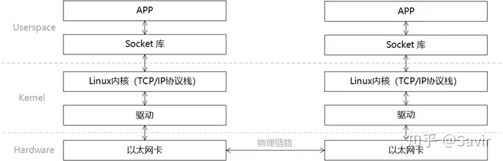
When describing the software and hardware relationship in the communication process, we usually divide the model into Userspace, Kernel, and Hardware. Userspace and Kernel actually use the same physical memory, but for security reasons, Linux divides memory into user space and kernel space. The user layer does not have permission to access and modify the memory content of the kernel space and can only enter kernel mode through system calls. The memory management mechanism of Linux is relatively complex, and this article will not discuss it in detail.
A typical communication process based on traditional Ethernet can be layered as shown in the figure below:
The steps of a send-receive process are as follows:
- The sender and receiver establish a connection through the interface provided by the Socket library (which is essentially establishing a logical path between two nodes, allowing data to be sent from one end to the other along this path) and respectively allocate the send and receive Buffers in memory.
- The sending-end APP enters kernel mode through the Socket interface, the data to be sent is encapsulated layer by layer by the TCP/IP protocol stack, and finally copied by the CPU into the Socket Buffer.
- The sender, through the network card driver, informs the network card that data can be sent. The network card will use DMA to copy the encapsulated data packet from the buffer to the internal cache, and then send it to the physical link.
- After the network card on the receiving end receives the data packet, it places the data packet into the receive buffer, and then the CPU will parse the packet layer by layer through the TCP/IP protocol stack in the kernel to extract the valid data.
- The receiving end APP enters kernel mode through the Socket interface, and the CPU copies data from kernel space to user space.
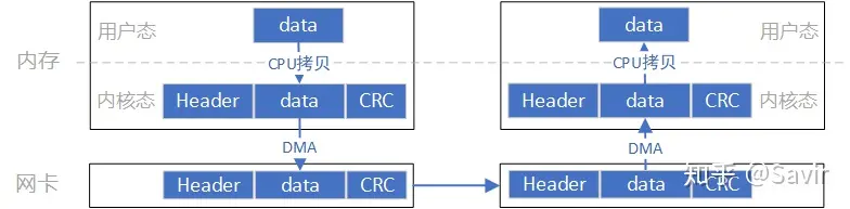
The data flow of this model is roughly like the one shown in the above diagram. First, the data needs to be copied from user space to kernel space, and this copying is done by the CPU, which copies the data block from user space to the Socket Buffer in kernel space. The software TCP/IP protocol stack in the kernel adds headers and checksum information for each layer to the data. Finally, the network card copies the data from memory via DMA and sends it to the peer’s network card through the physical link.
And the opposite process occurs at the remote end: the hardware performs a DMA copy of the packet into memory, then the CPU parses and verifies the packet layer by layer, and finally copies the data to user space.
The key points in the above process are that the CPU needs to be involved in copying data from user space to kernel space, as well as the packet assembly and parsing, which also requires full CPU involvement. In cases of large data volumes, this will place a heavy burden on the CPU.
Let’s take a look at how RDMA “frees” the CPU.
# RDMA
In the same scenario where one end sends and the other receives, we divide the RDMA layered model into two parts: “control path” and “data path”. The control path needs to enter kernel mode to prepare the memory resources required for communication, while the data path refers to the process during the actual data interaction. The layered relationship of this process is shown in the figure below:
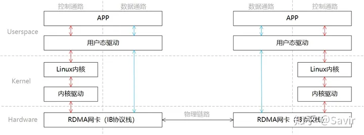
Like Socket, we briefly describe the communication process:
- The sender and receiver respectively enter kernel mode through the control path to create the memory resources needed for communication.
- On the data path, the receiving end APP informs the hardware to prepare to receive data and tells the hardware where to place the received data in memory.
- In the data path, the sending end APP notifies the hardware to send data, informing the hardware which memory the data to be sent is located in.
- The sending RDMA network card moves data from memory, assembles the packet, and sends it to the peer.
- The peer receives the packet, parses it, and writes the payload into memory via DMA. Then it notifies the upper-layer APP in some way, informing it that the data has been received and properly stored in the designated location.
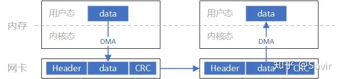
The data flow in this process is roughly as shown in the above diagram. Compared with Socket, we can clearly see that data sending and receiving bypass the kernel and the data exchange process does not require CPU participation, the assembly and parsing of packets are completed by hardware.
Through the above comparison, we can clearly appreciate the advantages of RDMA, which not only frees the CPU from packet encapsulation and parsing but also reduces the power and time consumption of CPU data copying. It should be noted that this article only describes the SEND-RECV process, while the unique and more efficient WRITE/READ semantics of RDMA technology will be introduced in subsequent articles.
In the next article, we will introduce some important and fundamental concepts in RDMA technology.