# 1. SME Introduction
Scalable Matrix Extension SME is built on the basis of Scalable Vector Extensions (SVE and SVE2) and adds the capability to efficiently handle matrices. The main features include:
- Calculate the SVE vector’s outer product
- Matrix tile storage
- Loading, storing, inserting, and extracting tile vectors (including dynamic transposition)
- Streaming SVE mode
The table below summarizes the main features of SME, SVE, and SVE2:
| SME | SVE | SVE2 |
|---|---|---|
| Streaming SVE Mode | NEON DSP++ | Scalable Vector |
| Dynamic Matrix Transpose | Multi-Precision Arithmetic | Per-Lane Predication |
| Vector Cross Product | Match Detection and Histogram | Gather-load and Scatter-store |
| Load, store, insert, and extract matrix vectors | Non-temporal scatter/gather | Predict vectorization |
| Bitwise Permute | ML Extension (FP16 + DOT) | |
| AE, SHA3, SM4, Crypto | V8.6 BF16, FP and Int8 support |
SME has defined the following new features:
- New architecture state, can be used to store two-dimensional matrix tile
- Streaming SVE mode, supports SVE2 instructions where the execution vector length matches the tile length.
- New instruction to accumulate (or decrement) the outer product of two vectors into a matrix tile.
- New load, store, and move instructions: Vectors can be written to a row or column of a matrix tile, or a row or column of a matrix tile can be read into a vector.
Similar to SVE2, SME is also an extension that supports scalable vector length, enabling vector length agnosticism (VLA), per-lane predication, predication-driven loop control, and management functions.
# 2. Streaming SVE mode
SME introduced the Streaming SVE mode, which implements a subset of the SVE2 instruction set and adds new SME-specific instructions.
Streaming SVE mode supports high-throughput streaming data processing for large datasets, and streaming data usually has simple loop control flow and limited conditionality.
In Non-streaming SVE mode, the complete SVE2 instruction set is supported, typically handling complex data structures and complex judgments.
Streaming SVE Mode and Non-streaming SVE Mode
Most SME instructions are only available in Streaming SVE mode. The streaming vector length (SVL) in Streaming SVE mode may differ from the non-streaming vector length (NSVL).
The expectation is: SVL should be longer than or equal to NSVL, that is, SVL >= NSVL. For example, the length of NSVL can be 128-bit, while the length of SVL can be 512-bit.
The SVL of SME can be 128-bit, 256-bit, 512-bit, 1024-bit, or 2048-bit. SVL needs to be a power of 2, and NSVL needs to be a multiple of 128.
Similar to SVE2, the software can control the SMCR_ELx.LEN register bit to set the effective SVL length that EL1, EL2, EL3 want to use (it can be set shorter than the SVL supported by the hardware).
For more information on the Streaming SVE mode, refer to section B1.4.6 of the Arm Architecture Reference Manual (A-profile architecture).
# 3. Switch between Non-streaming and Streaming SVE modes
If the CPU hardware implementation supports both Streaming SVE mode of SME and Non-streaming SVE mode of SVE2, applications can dynamically switch between these two operation modes based on their needs.
Provide an independent operating mode for SME, allowing CPU hardware implementations to offer different vector lengths for the same application. For example, a CPU hardware implementation can choose to support a longer Streaming SVE mode vector length and optimize the hardware for stream operations suitable for high throughput.
Applications can easily switch dynamically between Streaming SVE mode and Non-streaming SVE mode. The PSTATE.{SM, ZA} bits introduced by SME can enable and disable Streaming SVE mode and SME ZA storage:
- SM: Enable and disable Streaming SVE mode
- ZA: Enable and disable ZA storage access
You can use the MSR/MRS instructions to operate the Streaming Vector Control Register (SVCR) to set and read the PSTATE.{SM, ZA} bits, with specific operations as follows:
MSR SVCRSM, #<imm> MSR SVCRSM, #MSR SVCRZA, #<imm>MSR SVCRSMZA, #<imm>
The SMSTART instruction is an alias for the MSR instruction that sets PSTATE.SM and PSTATE.ZA.
SMSTART: Simultaneously enable Streaming SVE mode and ZA storage accessSMSTART SM: Enable Streaming SVE modeSMSTART ZA: Enable ZA storage access
The SMSTOP instruction is an alias for the MSR instruction that clears PSTATE.SM and PSTATE.ZA.
SMSTOP: Simultaneously disable Streaming SVE mode and ZA storage accessSMSTOP SM: Disable Streaming SVE modeSMSTOP ZA: Disable ZA storage access
The diagram below shows how the application switches between Streaming SVE mode and Non-streaming SVE mode:
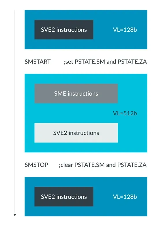
Application switching Streaming SVE mode and Non-streaming SVE mode
For more information on switching between Streaming SVE mode and Non-Streaming SVE mode using SMSTART and SMSTOP, please refer to sections C6.2.327 and C6.2.328 of the Arm Architecture Reference Manual on A-profile architecture.
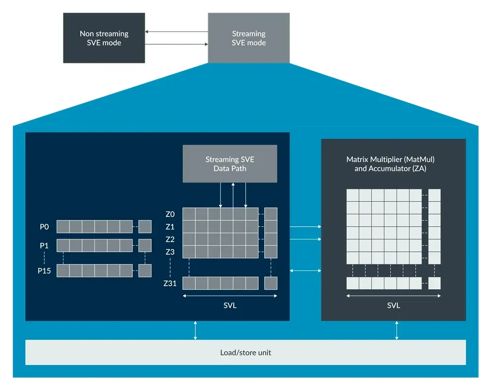
# 4. SME Architecture Status
Similar to SVE2, in Streaming SVE mode, it has Z0-Z31 vector registers and P0-P15 predicate registers.
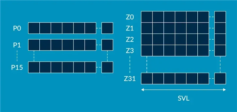
The lowest numbered SVE vector register Zn also holds fixed-length Vn, Qn, Dn, Sn, Hn, and Bn registers.
When entering Streaming SVE mode (PSTATE.SM changes from 0 to 1) or exiting Streaming SVE mode (PSTATE.SM changes from 1 to 0), all these registers will be zeroed.
Most non-streaming SVE2 instructions can be used in Streaming SVE mode, but may use different vector lengths (streaming mode uses VSL length, non-streaming mode uses NVSL length). The RDSVL instruction can be used to read the current effective vector length VL.
| |
Note
Because SME supports Vector Length Agnostic (VLA), in Streaming SVE mode, software rarely needs to explicitly read the SVL vector length. In Non-streaming SVE mode, the RDSVL instruction is usually used to determine the value of SVL.
# 5. ZA array
The newly introduced ZA (Z Array, ZA Storage) in SME is a two-dimensional (2D) square array with a size of SVL x SVL. It is called Z Array because the length of its rows and columns is consistent with the Zn registers in Streaming SVE mode.

ZA array
For example: If the vector length in Streaming SVE mode is 256-bit, i.e., the length of the Zn register is 256-bit, then the size of ZA is 256/8 bytes x 256/8 bytes.
The ZA array can be accessed in the following way:
- ZA array vector access
- ZA tiles
- ZA tile slices
# 5.1 ZA array vector access
A row of the ZA array can be accessed as a vector of SVL length, and this vector can contain elements with data type lengths of 8-bit, 16-bit, 32-bit, 64-bit, or 128-bit, such as 32-bit fp32 floating-point numbers.
| |
Among them, B, H, S, D, Q represent 8-bit, 16-bit, 32-bit, 64-bit, 128-bit, respectively.
The number of ZA array vectors is the same as the number of bytes in SVL. For example, if SLV is 256-bit, then the number of ZA array vectors is 32, and the range of N is from 0 to 31.
To support context switching, SME introduces new LDR and STR instructions for loading and storing a ZA array vector from memory.
| |
# 5.2 ZA tiles
ZA tile is a square two-dimensional submatrix within ZA. The width of a ZA tile is always SVL, which is the same as the width of the ZA array.
How many usable ZA tiles ZA can be divided into is determined by the size of the data type of the elements:
| Element Data Type Size | Tile Quantity | Tile Name |
|---|---|---|
| 8-bit | 1 | ZA0.B |
| 16-bit | 2 | ZA0.H-ZA1.H |
| 32-bit | 4 | ZA0.S-ZA3.S |
| 64-bit | 8 | ZA0.D-ZA7.D |
| 128-bit | 16 | ZA0.Q-ZA15.Q |
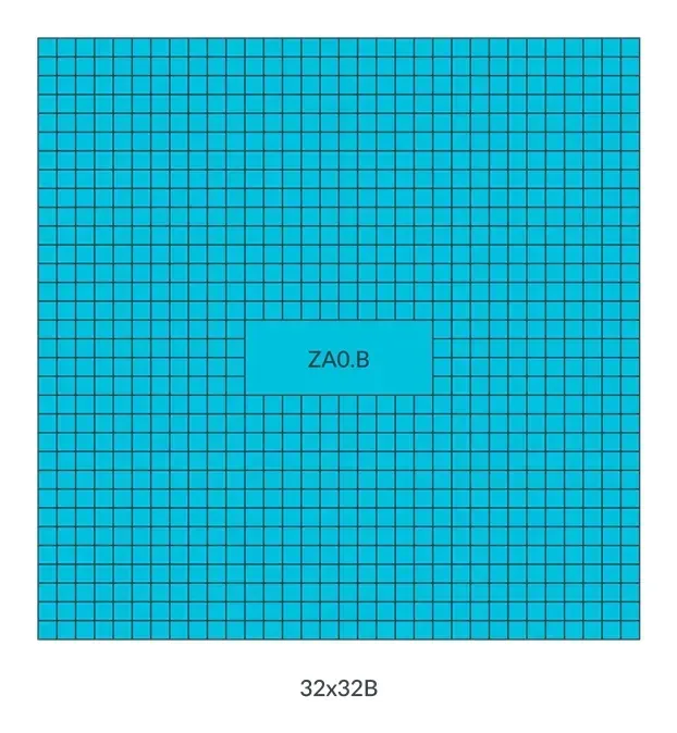
- When the element data type is 8-bit, ZA can only be accessed as a ZA tile (ZA0.B).
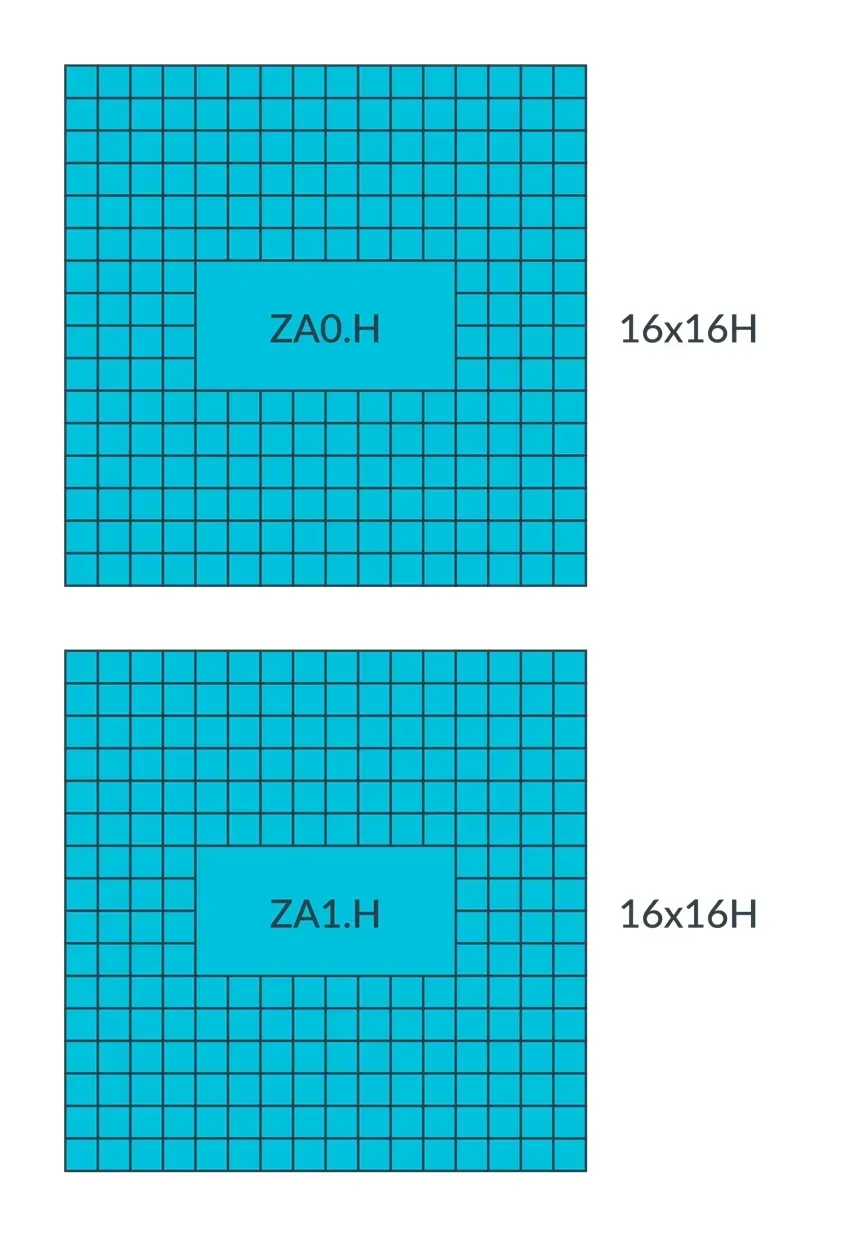
- When the element data type is 16-bit, ZA can be accessed as 2 ZA tiles (ZA0.H and ZA1.H).
- When the element data type is 32-bit, ZA can be accessed as 4 ZA tiles (ZA0.S to ZA3.S).
- When the element data type is 64-bit, ZA can be accessed as 8 ZA tiles (ZA0.D to ZA7.D).
- When the element data type is 128-bit, ZA can be accessed as 16 ZA tiles (ZA0.Q to ZA15.Q).
For example, if SVL is 256-bit and the element data type size is 8-bit, then ZA can be considered as ZA0.B, or it can be seen as 32 vectors (32 rows, each row size is 32 x 8-bit, i.e., 32 elements per row).
If SVL is 256-bit and the element data type size is 16-bit, then ZA can be considered as 2 ZA tiles (ZA0.H and ZA1.H), with each tile considered as 16 vectors (16 rows, each row size is 16 x 16-bit, i.e., 16 elements per row).
The advantage of doing this is to fully utilize ZA storage. In practical applications, for example, when the SVL is 256-bit, the element data type size is 32-bit, and the size of ZA is 256-bit x 256-bit, to perform an outer product operation on vectors in two Z registers, the outer product result is a 2D array of 8 x 8 floating-point numbers. This outer product only requires 1/4 of the storage space of ZA. By dividing ZA into 4 ZA tiles, ZA storage can be fully utilized.
# 5.3 ZA tile slices
A ZA tile can be accessed as a whole or in the form of individual ZA tile slices.
When accessed as a whole, instructions can be accessed using the name of the tile:
| |
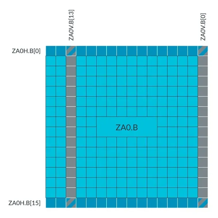
A ZA tile slice is a one-dimensional array composed of continuous elements in the horizontal or vertical direction of its ZA tile, that is, a row or a column in the ZA tile.
Accessing a vector of a ZA tile is reading and writing a ZA tile slice:
- Horizontal or vertical ZA tile slice access is indicated by the
HorVsuffix following the ZA tile name. - A specific ZA tile slice is represented by an index, indicated by the slice index
[N]following the ZA tile name.
For example, if the SVL is 128 bits and the element data type size is 8-bit, then its horizontal and vertical ZA tile slice can be represented as shown in the figure below:
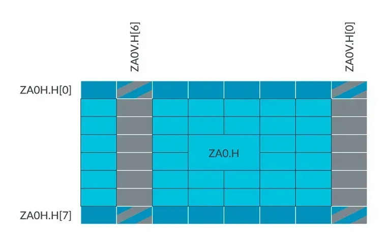
For example, if the SVL is 128 bits and the element data type size is 16-bit, then its horizontal and vertical ZA tile slice can be represented as shown in the figure below:
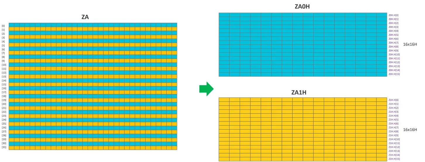
In order to improve the efficiency of hardware access to ZA tile and ZA tile slices, the ZA tile slices of a ZA tile are interleaved.
The image below shows an example of this interleaved arrangement. In this example, SVL is 256 bits, and the element data type size is 16 bits. This means that ZA can be viewed as two ZA tiles (ZA0H and ZA1H) and has interleaved horizontal tile slices:
The figure below shows a mixed view of the horizontal and vertical ZA tile slice sizes for different element data types:

The left columns show the different processing methods for each row of the ZA memory.
Set SIZE as the size of vector elements, where SIZE is 1, 2, 4, 8, 16, representing data types B, H, S, D, or Q, respectively.
Set NUM_OF_ELEMENTS as the number of elements in the vector, i.e., bytes_of(SVL)/SIZE.
Horizontal tile slice, ZAnH.<B|H|S|D|Q>[m] accesses a vector that contains a whole row (m x SIZE + n) in ZA storage. The vector contains elements of data type B, H, S, D, or Q.
Vertical tile slice, ZAnV.<B|H|S|D|Q>[m] accesses a vector that contains the entire column (m x SIZE) in ZA storage. This vector contains elements of data type B, H, S, D, or Q.
ZAnV.[m] accesses a vector containing column (m x SIZE) and row elements (i x SIZE + n), where i ranges from 0 to NUM_OF_ELEMENTS-1. This vector contains elements of data types B, H, S, D, or Q.
Be careful with overlapping when applying mixed element data type sizes and horizontal and vertical tile slices.
For more information on ZA Array, ZA array vectors, tile, and tile slices, refer to sections B1.4.8 to B1.4.12 of the Arm Architecture Reference Manual for the A-profile architecture.
# 6. Instructions supported in Steaming SVE mode
Some instructions have limitations in Streaming SVE mode:
- Some SVE/SVE2 instructions become illegal to execute
- Gather-load and Scatter-store instructions
- Use the SVE2 instruction of the First Fault register
- Most NEON instructions become UNDEFINED
For more information about instructions affected by the Streaming SVE mode, please refer to the document “Arm Architecture Reference Manual.”
SME has added several new instructions, including:
- Matrix outer product and accumulate or subtract instructions, including FMOPA, UMOPA, and BFMOPA.
- SVE2 vector registers (Z0-Z31) serve as the row and column inputs for outer product operations.
- ZA storage stores the output results of the two-dimensional matrix tile.
- Instructions for performing addition operations with the SVE2 Z vector and the rows or columns of ZA
- Instruction for clearing ZA tiles
- Added some instructions that can be used in both Streaming and Non-streaming modes.
# 7. SME Directive
The main SME commands for operating ZA storage include:
- Calculate the cross product of two vectors, and then accumulate or decrement, and place the result into an instruction of a ZA tile.
- Instructions to store or load SVE vectors (Z registers) into or from rows or columns of the ZA tile
- In the horizontal or vertical direction, an SVE vector and ZA tile addition instruction
- An instruction to add a multiple of the vector length in Streaming SVE mode to a scalar register
# 7.1 Outer Product and Accumulate or Subtract Instructions
In order to help understand outer product and accumulate or subtract instructions, let’s see how to use the outer product operation to perform matrix multiplication.
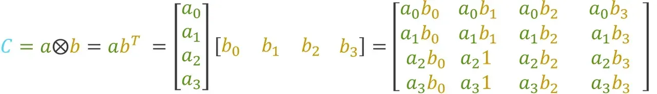
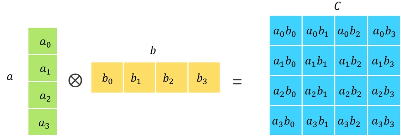
Calculating the outer product of two vectors a and b will yield a result matrix C containing the outer product:
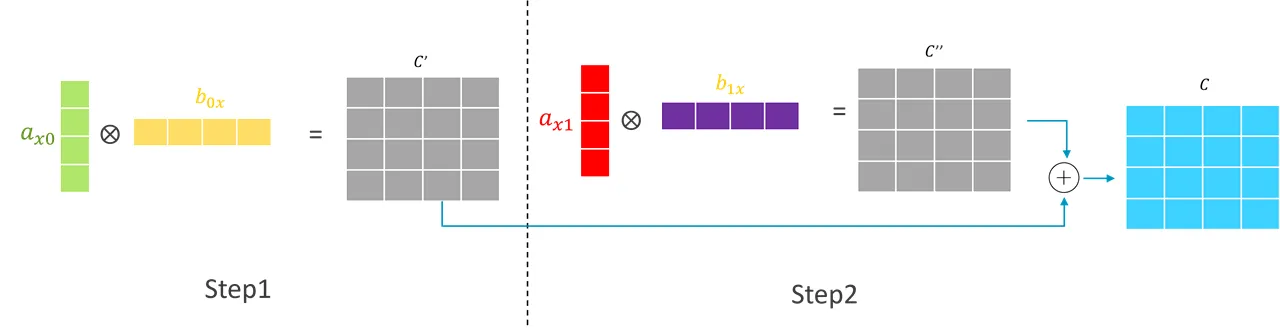
Now consider the matrix multiplication operation of two matrices a and b:

This matrix multiplication can be achieved by calculating two outer product operations and accumulating the two resulting matrices (which is the commonly used handwritten calculation method), as shown in the diagram below:
SME introduced efficient outer product and accumulate or subtract instructions for the following data types:
- 8-bit, 16-bit integers
- FP16, BF16, FP32, and FP64 floating point numbers
These instructions calculate the outer product of two vectors in two Z vector registers (Zn and Zm), accumulate or subtract the resulting array with the existing data in a ZA tile (ZAda), and store the result in the same ZA tile (ZAda). Each source vector is independently predicated by the corresponding control predicate registers (Pn and Pm).
| Output Array | Input Vector | Description | Example |
|---|---|---|---|
| INT32 | INT8, INT8 | Store the sum of the outer products of four INT8s into each INT32 element | SMOPA or SMOPS or UMOPA or UMOPS: Signed or unsigned integer outer product sum, and accumulate or subtract. For example: UMOPS <ZAda>.S, <Pn>/M, <Pm>/M, <Zn>.B, <Zm>.B |
| INT32 | INT16, INT16 | Store the sum of the outer product of two INT16 in each INT32 element | SMOPA or SMOPS or UMOPA or UMOPS: Signed or unsigned integer outer product sum, and accumulate or subtract. For example: UMOPS <ZAda>.S, <Pn>/M, <Pm>/M, <Zn>.H, <Zm>.H |
| INT64 | INT16, INT16 | If FEAT_SME_I16I64 is implemented, the sum of the outer products of four INT16s is stored in each INT64 element | SMOPA or SMOPS or UMOPA or UMOPS: signed or unsigned integer outer product sum, and accumulate or subtract. For example: UMOPS <ZAda>.D, <Pn>/M, <Pm>/M, <Zn>.H, <Zm>.H |
| FP32 | BF16, BF16 | Store the sum of two BF16 outer products into each FP32 element | BFMOPA or BFMOPS: BFloat16 outer product sum, with accumulation or subtraction. For example: BFMOPS <ZAda>.S, <Pn>/M, <Pm>/M, <Zn>.H, <Zm>.H |
| FP32 | FP16, FP16 | Store the sum of two FP16 outer products into each FP32 element | FMOPA or FMOPS: Half-precision floating-point outer product sum, and accumulate or subtract. For example: FMOPS <ZAda>.S, <Pn>/M, <Pm>/M, <Zn>.H, <Zm>.H |
| FP32 | FP32, FP32 | Simple FP32 outer product | FMOPA or FMOPS: Floating-point outer product and accumulate or subtract. For example: FMOPS <ZAda>.S, <Pn>/M, <Pm>/M, <Zn>.S, <Zm>.S |
| FP64 | FP64, FP64 | If FEAT_SME_F64F64 is implemented, perform a simple FP64 outer product | FMOPA or FMOPS: Floating point outer product and accumulate or subtract. For example: FMOPS <ZAda>.D, <Pn>/M, <Pm>/M, <Zn>.D, <Zm>.D |
# 7.1.1 FP32, FP64 outer product and accumulate or subtract instructions
Instructions where the input vectors and output arrays have the same data type (FP32, FP64) are relatively simple.
The following example demonstrates FP32 type outer product with accumulation or subtraction instructions.
| |
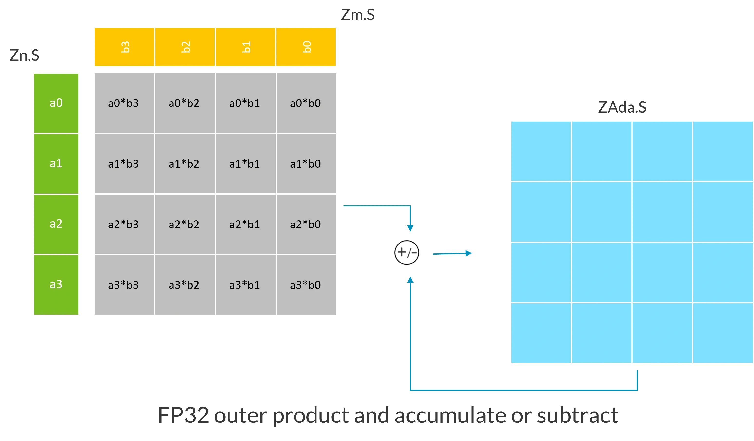
In this example, assuming the SVL vector length is 128, Zn.S and Zm.S contain vectors composed of 4 FP32 numbers, this instruction calculates the outer product of Zn.S and Zm.S, the result of the outer product is the gray matrix in the figure, then accumulates or subtracts this outer product result with the existing values in the ZA tile ZAda.S, and stores the result in the same ZA tile.
# 7.1.2 FP16, BF16, INT16, INT8, I16I64 type outer product and accumulate or subtract instructions
Because these instructions will expand the data type of the calculation results, these operations are not as straightforward as the previous FP32 and FP64 type instructions.
- BF16 instruction calculates the outer product of two BF16s, expands the result type to FP32, and then destructively adds or subtracts the result with the target tile.
- INT8 instructions compute the sum of the outer product of four INT8s, expanding the result type to INT32, and then perform destructive addition or subtraction of the result with the target tile.
- INT16 instruction calculates the outer product sum of two INT16s, expands the result type to INT32, and then performs a destructive add or subtract with the target tile.
- FP16 instructions calculate the sum of the outer product of two FP16s, expand the result type to FP32, and then perform destructive addition or subtraction of the result with the target tile.
- If FEAT_SME_I16I64 is implemented, the I16I64 instruction calculates the sum of the outer products of four INT16s, expands the result type to INT64, and then destructively adds or subtracts the result with the target tile.
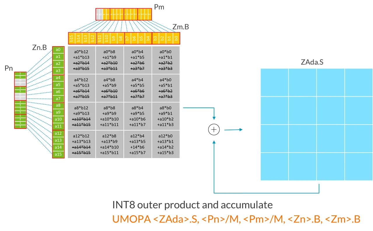
The following example demonstrates the operation of the INT8 UMOPA instruction with an SVL vector length of 128:
| |
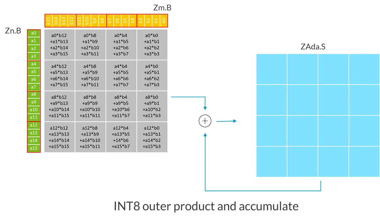
Each input register (Zn.B, Zm.B) is treated as a matrix containing 4x4 elements, which can be seen as blocks composed of 4 consecutive elements (as marked by the red lines in the diagram) that have been transposed.
In this example, because the SVL vector length is 128-bit:
- The first source vector
Zn.Bcontains a 4x4 submatrix of unsigned 8-bit integers. - The second source vector
Zm.B, contains a 4x4 submatrix of unsigned 8-bit integers. - UMOPA instruction calculates the sum of the 4x4 expanded 32-bit integer outer product, then destructively accumulates the integers in the target tile (ZAda).
More generally, the UMOPA instruction multiplies submatrices from the first source vector with submatrices from the second source vector. Each source vector contains a submatrix of unsigned 8-bit integers of size (SVL/32) x 4. The resulting (SVL/32) x (SVL/32) expanded 32-bit integer outer product is then destructively added to a 32-bit integer target tile.
The following example demonstrates the operation of a BF16 BFMOPA with an SVL of 128-bit:
| |
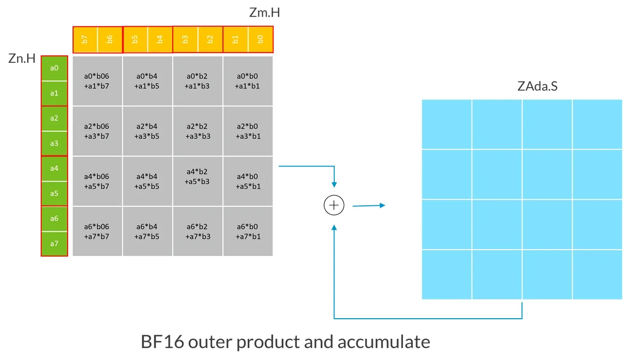
In this example, because the SVL vector length is 128-bit:
- The first source vector
Zn.H, contains a 4x2 submatrix of BF16 integers, which is expanded into single-precision floating-point numbers. - The second source vector
Zm.H, contains a 2x4 submatrix of a BF16 integer, which is expanded into a single-precision floating-point number. - BMOPA instruction calculates the sum of a 4x4 single-precision outer product, and then destructively accumulates it with the single-precision floating-point numbers in the target tile (ZAda).
More generally speaking, the BFMOPA instruction expands the type of the (SVL/32) x2 BF16 submatrix stored in the first source vector to single precision, expands the type of the 2x (SVL/32) BF16 submatrix stored in the second source vector to single precision, and multiplies these two submatrices. Then, the resulting (SVL/32) x (SVL/32) single-precision outer product is destructively added to a single-precision target tile.
The following table shows the number of MACs (Multiply-Accumulate) for the corresponding data type performed by an outer product and accumulate or subtract instruction for several data types and SVL lengths:
| 128-bit | 256-bit | 512-bit | |
|---|---|---|---|
| FP32 | 16 | 64 | 256 |
| FP64 | 4 | 16 | 64 |
| INT8 | 64 | 256 | 1024 |
| INT16 | 32 | 128 | 512 |
| BF16 | 32 | 128 | 512 |
| FP16 | 32 | 128 | 512 |
# 7.2 SME Instructions with Predication
Each source vector can be independently predicated by its corresponding control predicate register:
- Outer product and accumulate or subtract instructions use Pn/M and Pn/M (without /Z form): Inactive source elements are treated as having a value of 0.
- Slice move command uses Pg/M: The Inactive elements in the target slice remain unchanged.
- Tile slice load instruction uses Pg/Z: Inactive elements in the target tile slice are set to 0.
- Tile slice store instruction uses Pg: Inactive elements that will not be written to memory.
Predication makes it easier to handle cases where the dimensions of the matrix are not a multiple of SVL.
For example, the instructions in the image below:
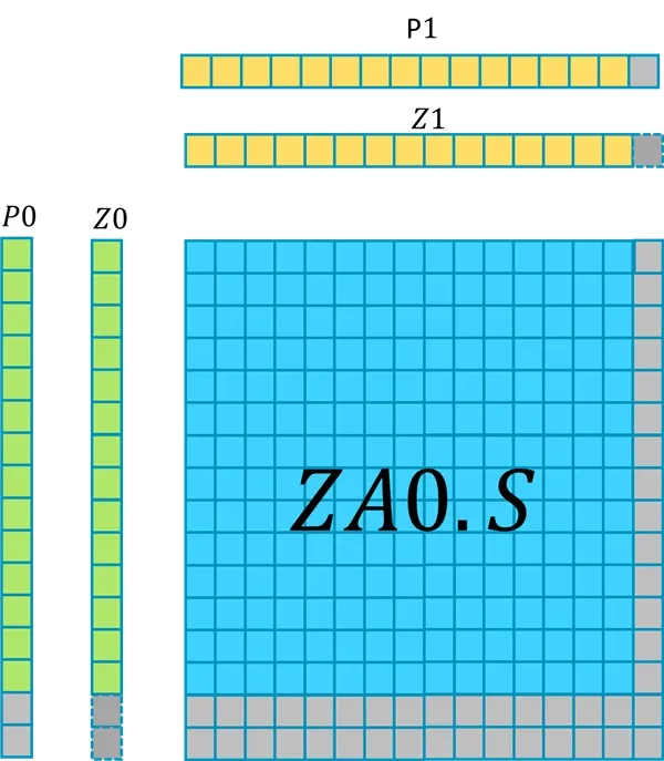
The input vector Z0 is predicated by P0, Z1 is predicated by P1.
In this example:
- SVL vector length is 512-bit.
- The Z register contains a vector of 16 FP32 numbers.
- The last two elements in
P0are inactive. - The last element in
P1is inactive.
This instruction updates (16-2) x (16-1) FP32 elements in ZA0.S, because Pn/M is used, the remaining elements in ZA0.S remain unchanged.
The figure below shows more examples of predicated outer products with accumulation or subtraction. The underlined text in the figure indicates the parts of the calculation affected by inactive predicate elements.

# 7.3 ZA tile and addition operation with a Z vector
SME includes instructions to add a vector to the rows or columns of a ZA tile, and these instructions also support predication.
| Instruction | Description |
|---|---|
| ADDHA | Add the source vector to each horizontal slice of the ZA tile |
| ADDVA | Add the source vector to each vertical slice of the ZA tile |
For example:
| |
Will perform the following actions:

This ADDHA instruction adds each element of the source vector Z1 to the corresponding active element of each horizontal slice of the ZA0.S tile.
Elements in a Tile are predicated by a pair of governing predicates. An element in a horizontal slice can be considered active under the following conditions:
- It is TRUE for the element corresponding to the second governing predicate, and
- It corresponds to TRUE at the row number of the first governing predicate’s horizontal slice, and the inactive elements in the target tile remain unchanged.
# 7.4 Tile load, store, move instructions
SME tile load, store, move instructions can:
- Read data from memory and place it into a row or column of the ZA tile
- Write the row or column of the ZA tile into memory
- Move the row of the ZA tile to the SVE Z vector register
- Move the SVE Z vector register to a ZA tile row or column
# 7.4.1 Tile slice load and store instructions
The LD1B, LD1H, LD1S, LD1D, and LD1Q instructions load consecutive memory values into a ZA tile slice with 8-bit, 16-bit, 32-bit, 64-bit, or 128-bit elements, respectively.
The ST1B, ST1H, ST1S, ST1D, and ST1Q instructions store a ZA tile slice containing 8-bit, 16-bit, 32-bit, 64-bit, or 128-bit elements, respectively, into contiguous memory.
These instructions also support predication, for example:
| |
This LD1B instruction performs a predicated continuous byte read, reading data from memory at address (X1+X2) into the horizontal tile slice in ZA0 at row number (W0+imm). Inactive elements in the target tile slice are set to 0.
| |
This ST1H instruction executes a predicated continuous halfword store operation, storing the vertical tile slice in ZA1 with the column number (W0+imm) to the memory address (X1+X2*2), and elements that are inactive in the tile slice are not written to memory.
# 7.4.2 Tile slice move instruction
The MOV instruction (alias for the MOVA instruction) moves the value of a Z vector register to a ZA tile slice, or moves the value from a ZA tile slice to a Z vector register. This instruction operates on a single horizontal or vertical tile slice of a ZA tile with a specified element size. The row number/column number of the slice is specified by the slice’s retrieval register plus an immediate offset. Inactive elements in the target slice remain unchanged.
For example:
| |
Or
| |
This instruction moves the values in vector register Z0.B to the horizontal ZA tile slice ZA0H.B[W0,#imm], using P0 as the predication register. Inactive elements in the target tile slice remain unchanged.
# 7.5 ZA array vector load/store instructions
SME LDR instruction reads data from memory into a ZA array vector, SME STR instruction stores the values from a ZA array vector into memory. These instructions do not have predication functionality. They are primarily for saving/restoring ZA storage during software context switching. SME LDR/STR instructions can also be used in Non-streaming SVE mode when PSTATE.ZA is enabled. For example, the ZA array vector in the following STR instruction is specified by a vector selection register Wv (scalar register W) plus an optional immediate number (Wv+Imm). The address for accessing memory is: a scalar register as the base, plus the same optional immediate offset multiplied by the current vector length in bytes.
| |
# 7.6 ZA tile clear instruction
SME ZERO instruction can clear a group of 64-bit ZA tile:
| |
The ZERO instruction can zero out up to 8 ZA tiles named ZA0.D to ZA8.D. The tiles to be zeroed are specified by the mask in the instruction, while the remaining tiles remain unchanged.
This instruction can also be used in Non-streaming SVE mode when PSTATE.ZA is enabled.
If you want to clear the entire ZA array, you can use an instruction alias, ZERO {ZA}.
# 7.7 New SVE2 Instructions
The SME architecture extension has added some new SVE2 instructions, which can also be used in PE that implements SVE2 when in Non-streaming SVE mode. These instructions include:
- Select a predicate register or an all-false Predicate select instruction
- Reverse 64-bit double word element instruction
- Signed/Unsigned clamp to smaller/larger value vector instructions
The following introduces the Predicate select instruction.
# 7.7.1 PSEL Instruction
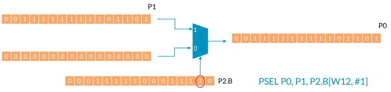
PSEL instruction selects a predicate register or all-false to the target predicate register, as follows:
| |
If the element specified in the second source predicate register (Pm) is True, this instruction places the content of the first source predicate register (Pn) into the destination predicate register (Pd), otherwise, it sets the value of the destination predicate register to all false. For example, the following instruction, assuming the value of W12 is 0:
| |
The [0]th element of the second source predicate register [W12+0] is False, so the target register P0 is set to all 0 (all-false), as shown in the figure below:

Now look at the following instruction, still assuming the value of W12 is 0, but this time the immediate offset is 1:
| |
The [1] element of the second source predicate register [W12+1] is True, therefore select the value of the first source predicate register to the destination register P0, as shown in the diagram below: